| Company History | Next | |
1959-1969 - The Early Years
 |  |
||||
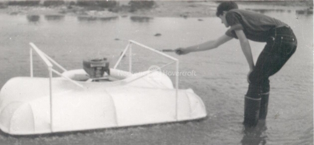
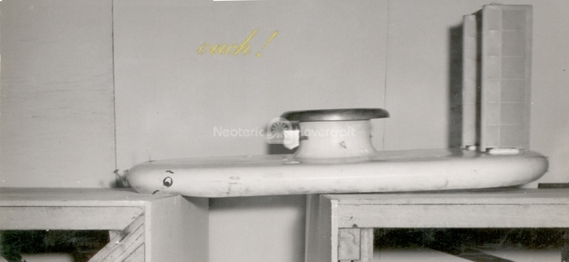
| Measuring over water drag on a statically hovering man-carrying hovercraft. This plenum chamber hovercraft used a 2-cycle 3½ HP lawn mower engine for lift. | Hovercraft experiments conducted at the Aeronautical Research Laboratory in Melbourne included crevasse jumping tests, as Australia had an active interest in Arctic transportation. This experiment consisted of a 60-foot long platform 8 feet wide and 4 feet off the hangar floor. Scale model hovercraft were catapulted along the center at various speeds and adjustable crevasse widths. At speed, the model could jump a crevasse of width almost 3/4 the length of the craft. Notice these tests were conducted on models that utilized the annular jet principle, before the days of hovercraft skirts. | ||||
In the early 1960s, while in the Royal Australian Air Force Air Training Corps, Chris found a ready supply of material with which to develop his hovercraft designs, and formed a club/business relationship with several fellow Cadets to help expedite his goal of creating a functional, personal-sized hovercraft. Together, Chris, Robert Wilson, Peter Kolf, and Alan Schwartz, as well as other members from outside the Air Training Corps — Eddy Thomas, Arthur Boyd, Bernard Sutcher, Laurie Fair and Sam Ciliauro - established the Hovercraft Research Organization. Their home base was located in a suburb of Melbourne at the Brunswick Boys’ Club, and the partners operated a Jazz Club to raise funds for their hovercraft research.
As an interesting side note, during this time they hired a new band, known as The Seekers, to perform at the Jazz Club. The very next week, The Seekers were called to England to perform the title song of the 1966 British film Georgy Girl, starring Lynn Redgrave. The title song became a hit single and was nominated for an Academy Award for Best Original Song. The Seekers were the first Australian popular music group to achieve significant chart and sales success in the United Kingdom and the United States.
In the mid-1960s, the Hovercraft Research Organization changed its name to Australian Air Cushion Vehicles Development. More than 50 Melbourne businesses agreed to donate materials to aid the group in the building of an experimental man-carrying model. Considered an extracurricular activity at the Air training Corps, the Cadet members worked after hours at the facility, and then at various backyard sheds and garages, crafting many different models and test rigs. Most valuable to the project at this time was Robert Wilson, who is still involved today with design and product development at Neoteric Hovercraft, Inc. David Atkins, who was introduced to the team by Arthur Boyd, is still the company’s aesthetic and ergonomic design engineer. Other members have gone on to such professions as Qantas Performance Engineer, Royal Australian Navy Engineer, Professor of Naval Architecture, General Motors Australia Design Engineer and Pfizer Australia Marketing Manager.
Construction of the hovercraft that introduced practical engineering design concepts took place at Melbourne University’s Mechanical Engineering School from 1962 to 1964; this craft was entered in the World’s First Hovercraft Race on March 14, 1964 in Canberra, Australia, the official name for this event was The World’s First Ground Effect Machine Race. The Canberra Branch of the Royal Aeronautical Society organized this event. Much to the chagrin of the Melbourne University’s Chancellor, it made its first run on his back lawn during an early Sunday morning in the early part of 1964. After participating in the first race, the group moved into W. Fitzgerald & Sons factory on Swanston Street in Melbourne, where development continued.
By 1968 Chris had left Aeronautical Research Laboratories and joined the family business along with Robert Wilson. Involvement at W. Fitzgerald & Sons lasted until 1969 when Robert Wilson resumed his engineering education and Chris Fitzgerald won a Rotary Club scholarship to study aeronautical engineering in the UK at the Farnborough Technical School and to work as an intern at British Hovercraft Corporation (formerly Saunders Roe), and then to travel the world to survey the latest in hovercraft technology.
In 1973, Australian Air Cushion Vehicles Development was renamed and incorporated as Neoteric Engineering Affiliates Pty Ltd. In 1975, Chris moved to the United States and incorporated Neoteric, Inc. in Indiana. It also traded as Neoteric USA Inc. and much later became Neoteric Hovercraft, Inc.
Following is A Photo History of Neoteric Hovercraft from 1959-1969
Since 1960, Neoteric Hovercraft, Inc. has collected hovercraft related publications, technical publications, photographs, 8mm and 16 mm early movies, videos and an extensive library of supplier’s catalogs. These libraries are constantly being cataloged. The 35 mm slide library has been cataloged and contains several thousand items. The goal is to eventually publish and/or to display them on the Neoteric website or at a Museum that will be created.
 |  |
 |
|||
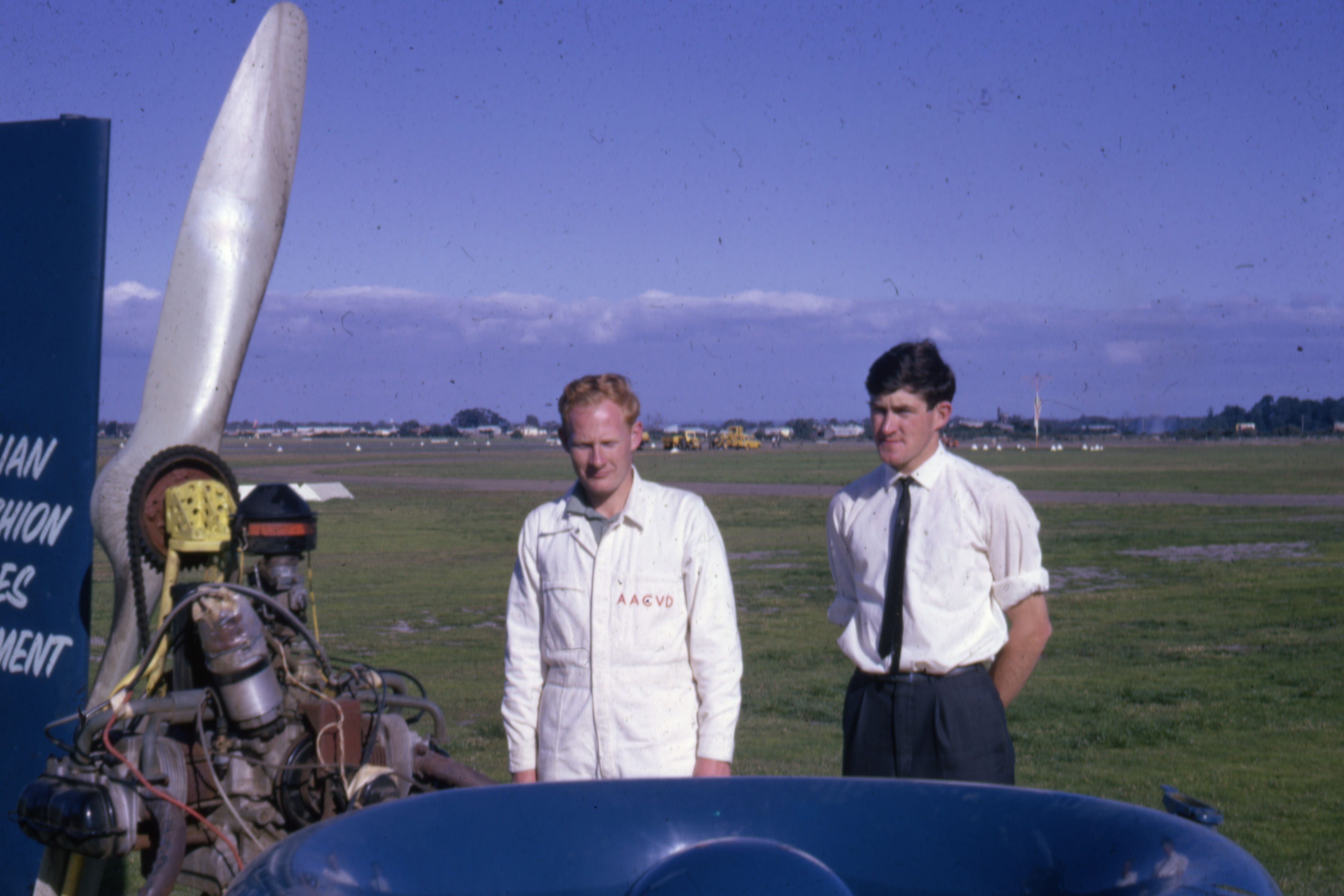
| The Melbourne Sun Newspaper, Australia | Australian Air Cushion Vehicles Development Craft #5 (AACVD5) on demonstration day at Moorabbin Airport, near Melbourne around 4th April 1966 | Rob Wilson (on the left) and Chris Fitzgerald (on the right) with their AACVD5 hovercraft on demonstration day at Moorabbin Airport, near Melbourne around 4th April 1966 | |||
Neoteric Australia slowly began providing technical services, prototype components, occasionally manufactured parts and to undertake experimental testing and model building to help the company. The company continues presently to operate its testing facility at Hastings, Victoria, Australia.
Research, development and experimentation continued: reverse thrust was developed and tested; trials undertaken and models constructed along with test rigs and full size hovercraft such as AACVD 5 (cannibalized in 1973). Some of the persons who assisted during this time were Dr. Laurence Doctors, James McCreedy and Bill Burke.
 |  |
||||
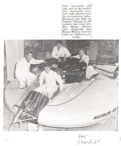
| The Melbourne Age newspaper, 23 June 1962 | The Melbourne Age Newspaper, 13 March, 1964 | ||||
 |  |
||||
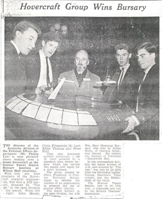
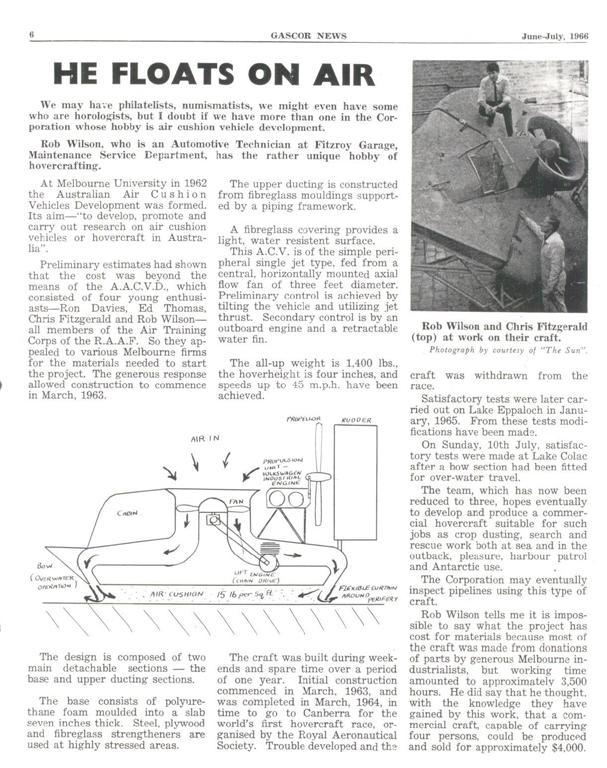
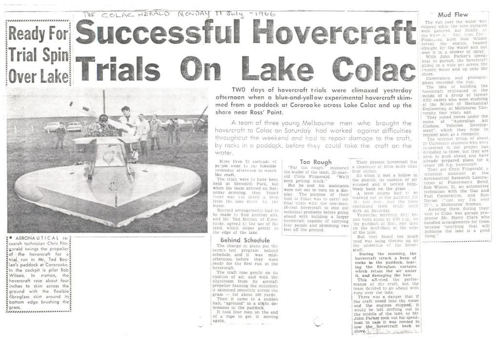
| Gascor News, June-July 1966 | The Colac Herald, Monday 11 July, 1966 | ||||
Chris Fitzgerald, Rob Wilson, Eddy Thomas and Ron Davies participated in the world's first hovercraft race in Canberra, Australia, as Australian Air Cushion Vehicles Development. Due to transmission difficulties the team was scratched from the race.
| A 16mm movie from The First Ground Effect Machine Race, 1964. |
1968 - 1971
During this time land was found and purchased. A small hangar/shed was constructed along the Hastings seashore, Victoria, Australia. This is a salt-water tidal mudflat area and ideal for prototype Hovercraft development and testing.
Chris surveyed world hovercraft developments under the sponsorship of Rotary International.
Rob Wilson, President, Neoteric Engineering Affiliates, Pty. Ltd, Australia; Technical Director, Neoteric Hovercraft, Inc. compiled the History of AACVD's developments. Rob Wilson graduated from the Footscray Institute of Technology in 1973. For more information about Rob Wilson's story, see this link. AACVD5 (version 5) was the first full sized man carrying hovercraft constructed by Neoteric, then known as Australian Air Cushion Vehicles Development. Many models and test rigs had been made and run in the years dating back to 1960, so a significant knowledge of the air cushion principle was available before AACVD5 was built. However, little was known about the construction of a full sized craft with its complex and inherent engine, transmission and operational environment problems - and nothing was known about flexible skirts. The learning curve was steep with many mistakes being made. It has been estimated that for every hour of the machine’s recorded total of 91 hours and 16 minutes of lift engine running time, 218 hours of repair, modification and maintenance was required. That’s nearly 20,000 hours of labor or about 2,000 hours per year over the life of the craft - not a minor effort for a small group of part timers. See this link for extensive detail about AACVD development's history.
| Company History | Next | |