| Company History | |
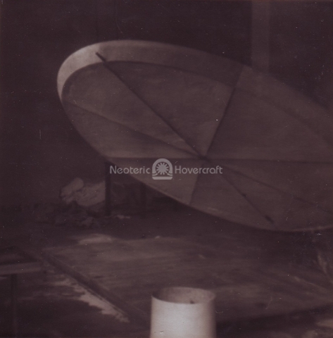
The first run of the AACVD5 was completed, in its original configuration of 12-foot diameter circular plan-form with annular air jets. Four segmental sections in the air jets actuated by a cockpit control stick enabled selective restriction of jet discharge area and hence tilted the craft to give forward, reverse or side force for low speed maneuvering. A 3-foot diameter, centrally mounted, cast aluminum axial fan was driven by a 350cc BSA single cylinder motorcycle engine with gearbox and single chain via a 90-degree bevel gearbox. No additional propulsion system was fitted. Fig. 1 through 5 shows the original construction.
 |  |
 |
|||
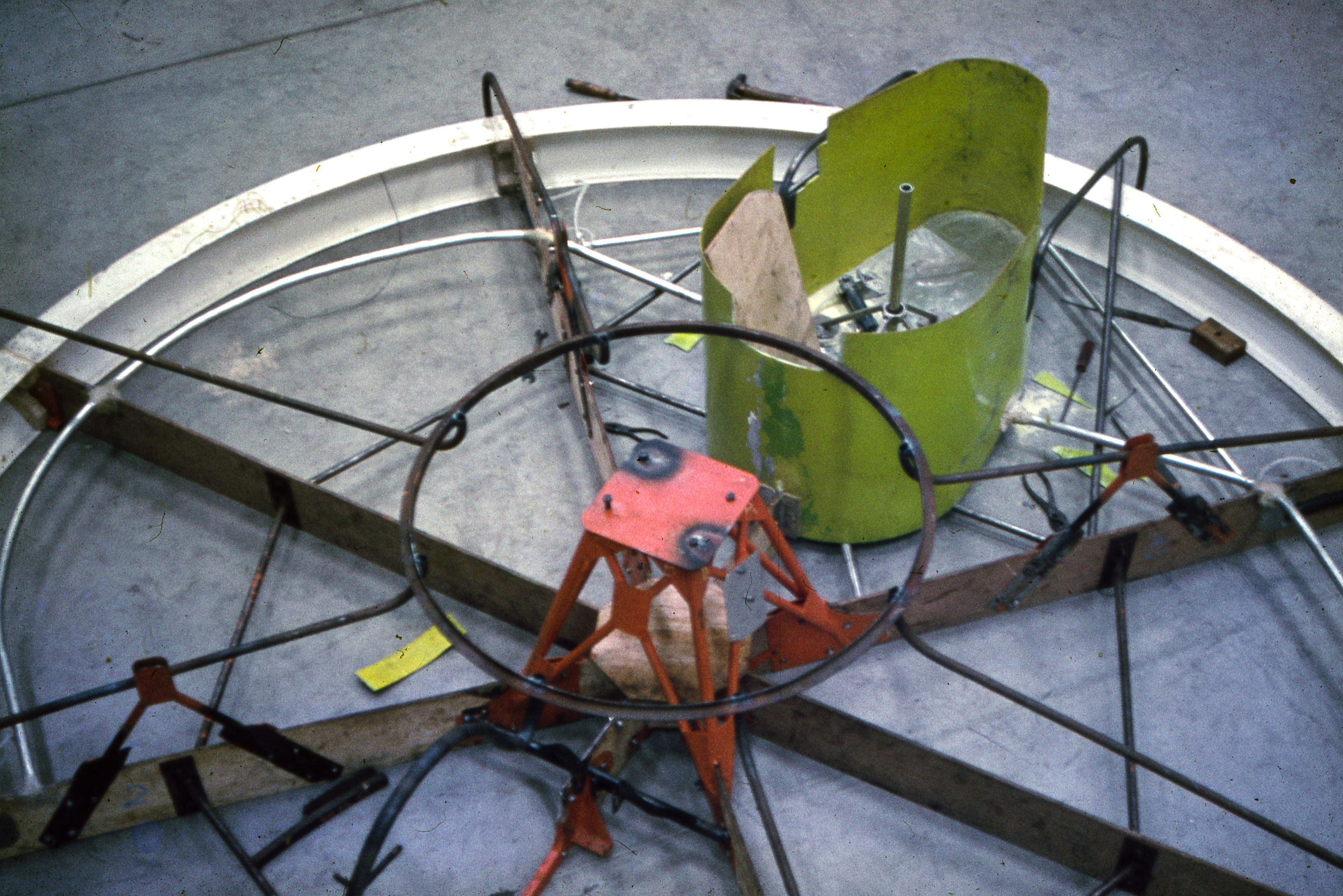
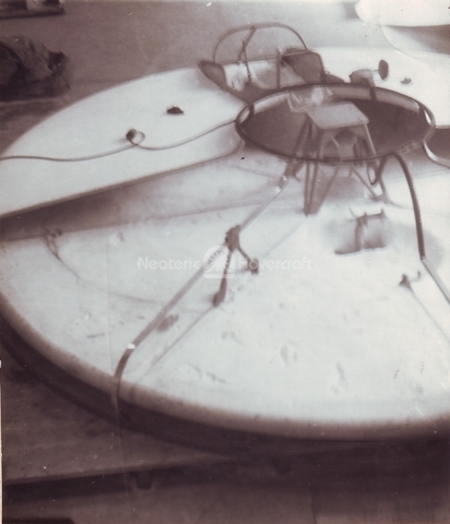
| Fig. 1: General layout, base, and upper duct frame Gearbox mount, cockpit molding, hydraulics and controlled jet pieces in position and ready for application of Urethane foam. |
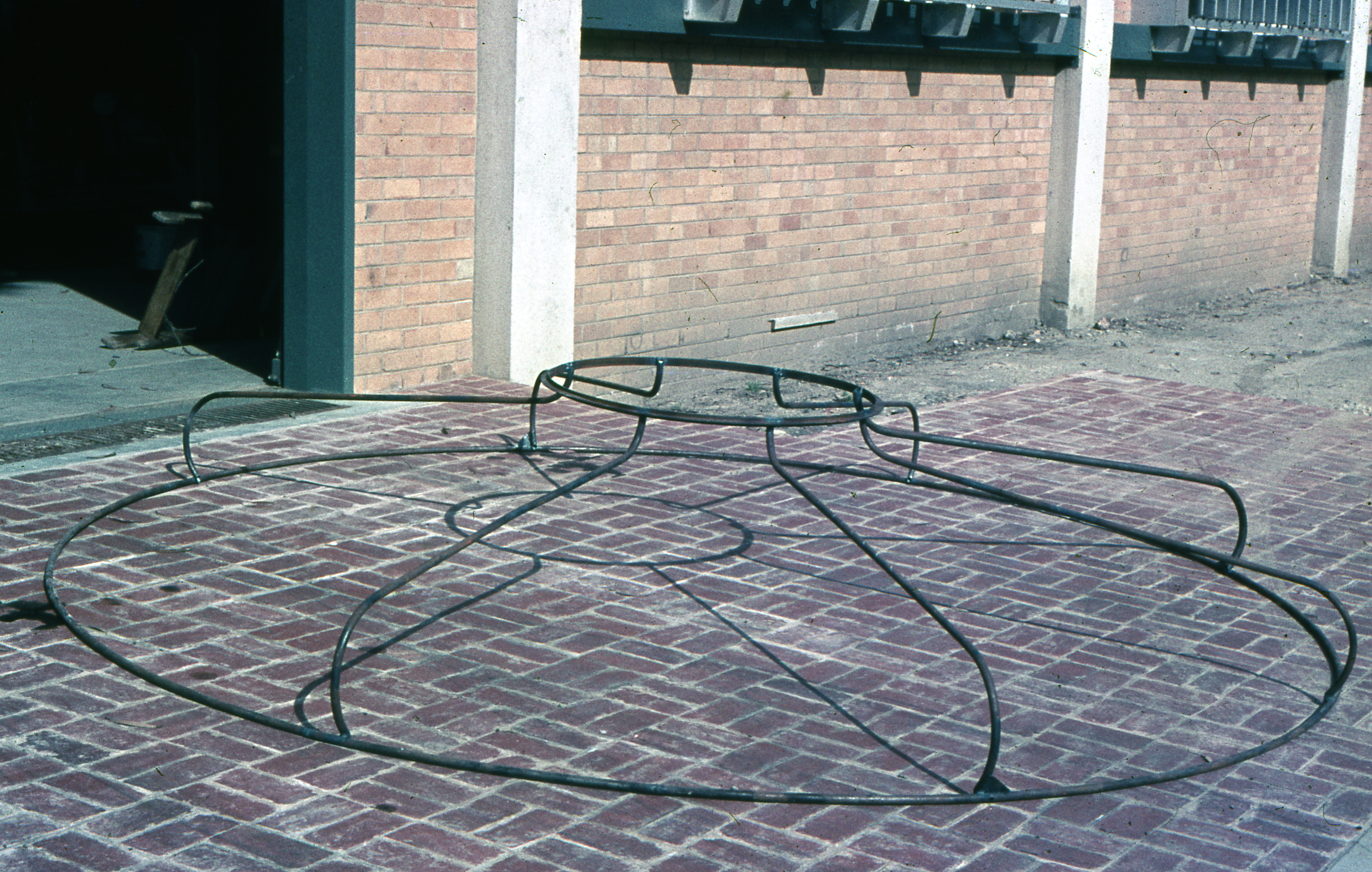
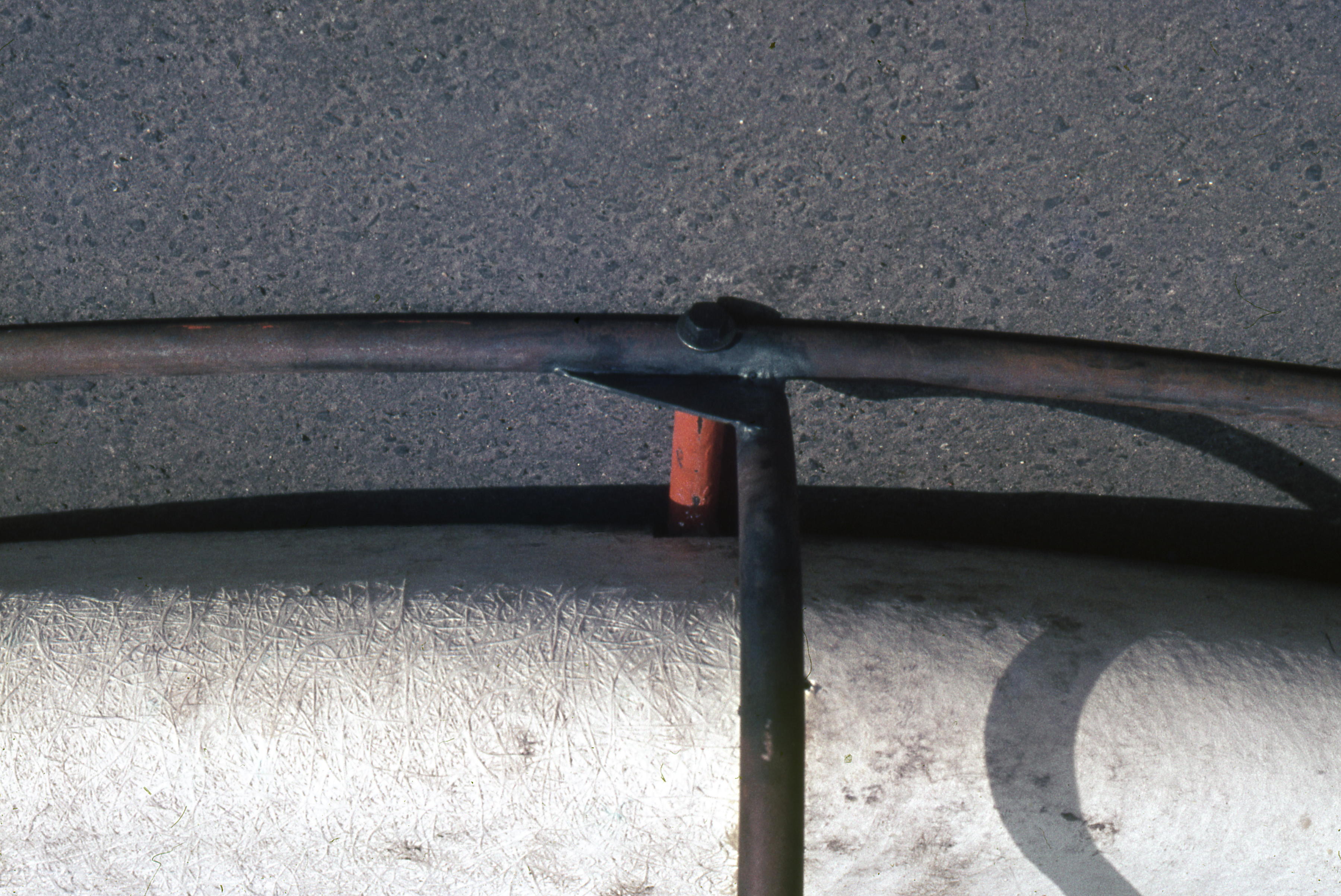
Fig. 2: Upper duct body frame support | Fig. 3: Annular air jet and lower/upper duct frame support | |||
 |  |
||||
| Fig. 4: Top of base showing air holes and uneven density of urethane foam after hand mixing, a 4-part process, and pouring. | Fig. 5: Bottom of base showing shrinkage of foam between ribs. |
||||
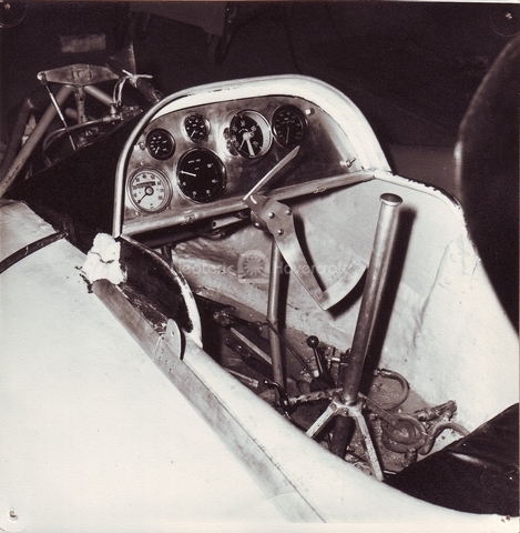
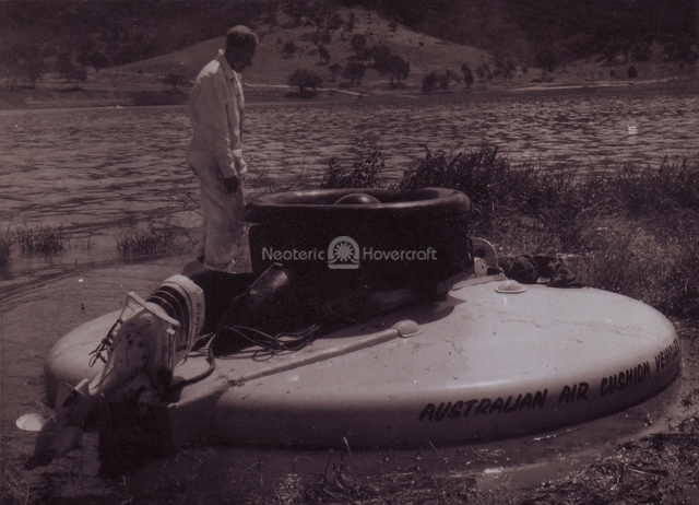
The AACVD5 was transported by road to Canberra for the World’s First Hovercraft Race. A 40hp outboard motor was fitted at the stern and a steerable/retractable water fin fitted to the bow. Fig. 6 shows the cockpit layout and Fig. 7 the outboard installation at that time. Numerous mechanical problems with the chain drive design limited running time to minutes between breakdowns. Fundamental trim problems negated the powerful thrust available from the outboard engine and the hovercraft was withdrawn from competition at an early stage.
 |  |
||||
| Fig. 6: Original cockpit layout Outboard engine and flap control hydraulics are fitted. |
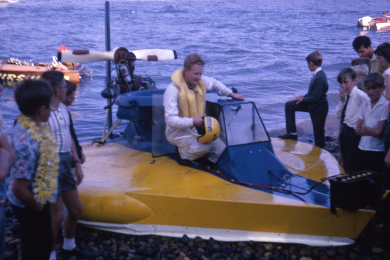
Fig. 7: Rob Wilson standing on a flotaing craft on Lake Burley Griffin in Canberra during preparation for the race The outboard installation, a 40 HP Johnson was used as we were trying to develop Hovercraft for towing water skiers. |
||||
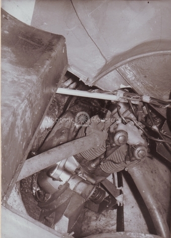
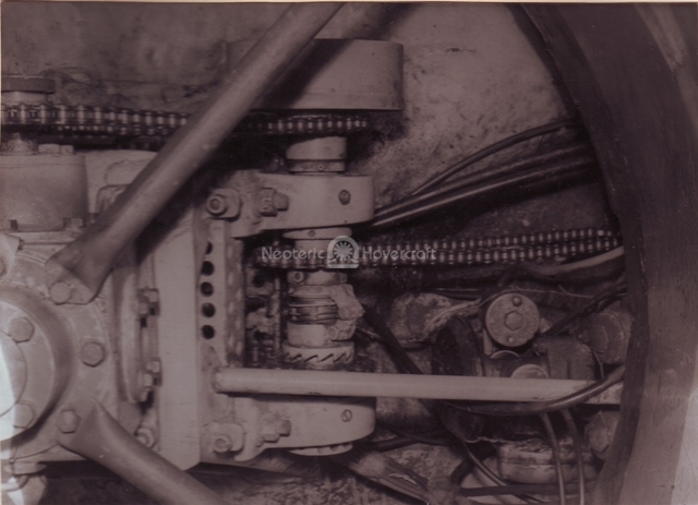
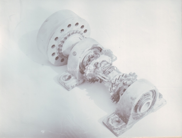
A more powerful 500cc Triumph 5T motorcycle engine was fitted to drive the lift fan (Fig. 8). No motorcycle gearbox or clutch was used and the chain drive was directly coupled to the fan right angle gearbox via a countershaft to give the necessary speed reduction and to reduce the center distance of the chain drive. A one-way overrunning clutch installed on the countershaft and chain-coupled to an aircraft starter motor provided electric starting. Due to the high fan inertia and direct drive, shock loads were high and numerous shaft failures occurred. The overrunning clutch on the starter drive was totally inadequate for the duty involved and soon burned out. After several transmission rebuilds and modifications, extending over many months, a reliable arrangement using a centrifugal clutch to decouple the fan and a saw-tooth clutch with a centrifugal weight release mechanism to disengage the starter was developed. Fig. 9 shows this arrangement.
 |
 |
 |
|||
| Fig. 8: Second lift engine installation A retractable Outboard engine and flap control hydraulics are fitted. |
Fig. 9a: Transmission installation Transmission installation showing mounts, right angle drive gearbox and vacuum pump. It was this transmission that caused us to fail at the first Hovercraft race. |
Fig. 9b: Fifth gearbox shaft From left: Centrifugal clutch, gearbox drive sprocket, starter motor dog clutch, starter sprocket & bearing. |
|||
The first flexible skirt was fitted. Given that the AACVD5 was a circular plan-form hovercraft, the skirt shape was conical, six inches deep and fitted to the outer air jet wall only. To avoid the anticipated snagging on obstacles due to the 45-degree skirt angle, elastic panels were built into the fabric. The air jet flaps, shown to be effective in tilting the craft in its original configuration, were retained but proved to be completely ineffective with a skirt fitted to the outer jet wall. Worst of all, the stretchable panels resulted in skirt flutter and severe craft vibrations.
In an effort to make the air jet controls effective, a second skirt was fitted to the inner jet wall. The stretchable panels on the outer skirt were mostly replaced. Unfortunately, the air jet controls were still ineffective and the inner skirt unstable, often sticking to the outer skirt, blocking airflow and causing loss of lift on that side of the craft.
Since the elastic panel skirt method of providing stretchability had been unsuccessful, a partially stretchable material for the outer skirt was tried.
In an attempt to continue water screw propulsion, it was decided to replace the heavy 180 pound, 40 horsepower Johnson outboard motor with a much lighter 18 horsepower outboard weighing 80 pounds. A new single 45-degree conical skirt with minimal stretchability and good abrasion resistance was installed, along with a reinforced higher cable travel lifting system. Simple flap type stability skirts were also fitted laterally and longitudinally. This layout is shown in Fig. 10 and Fig. 11. Water testing at Lake Eppalock showed that the relatively high thrust moments generated by the outboard propulsor could mot be matched by the much lower stabilizing moments generated by the circular air cushion. A trim balance between bow-in plough and stern scooping was impossible to control.
 |
 |
 |
||
| Fig. 10: Second lighter outboard installation being tested. | Fig. 11a: Fourth flexible skirt. | Fig. 11b: Close-up of under the skirt and lateral and longitudinal Stability members on fourth flexible skirt. |
||
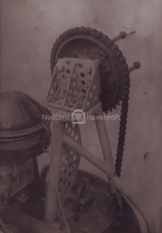
The original BSA lift engine was set up on a steel tubing frame to turn a 6 foot diameter wooden light aircraft propeller via a chain reduction drive. This propulsion unit was fitted to the craft and some thrust measurements recorded. The installation was unreliable but the basic concept of airscrew propulsion was shown to be viable.
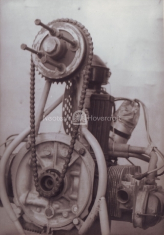
A 1200cc Volkswagen industrial engine was obtained and set up on a tubing frame as a pusher propulsion unit using the same propeller as that used in the BSA engine test. Direct chain drive was employed and weight minimized by discarding the VW flywheel, cooling system, generator and starter. Starting was by hand swinging the propeller and a magneto ignition system eliminated the need for a battery. Fig. 12 shows detail of this installation. The assembly was strapped to the craft, enabling easy removal for road transportation.
A large fin, operated by a foot-actuated hydraulic system, was fitted behind the propeller. To minimize the effects of plough-in and water spray, a triangular bow was made from steel tubing and covered with plywood, extending the craft length by 3 feet. A cabin with adequate headroom and a windscreen wiper/washer system was added.
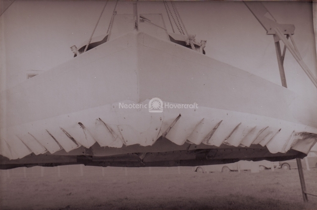
Because of the bow extension a new skirt was fitted. Initially this skirt was the same conical design as previously, except for straight sections along the bow. The skirt lifting cables were replaced by chains enclosed in tubes; skirt lift was subsequently proved to be largely ineffective and this system was abandoned. The straight skirt bow sections blew out and were replaced by convoluted fingers. It was found that the extra cushion lift generated by the bow section produced excessive bow-up trim; this was alleviated by restricting the air flow to this section via calibrated holes in the conical front section of the main skirt. Fig. 13 shows the bow section of this installation.
 |  |
 |
|||
| Fig. 12a: Detail of propulsion unit airscrew drive. | Fig. 12b: Detail of propulsion unit airscrew drive mounted to VW engine. | Fig. 13: Convoluted bow section of fifth flexible skirt fitted to increase lift load. | |||
Trials in a salt-water swamp at Point Cook in Melbourne proved the viability of the propulsion, skirt and control systems. These trials also introduced the crew to accelerated corrosion conditions inherent in salt-water operations.
A public demonstration at Devonport, Tasmania (Fig. 14a) provided experience in salt water with ocean swell conditions. A demonstration of how dangerous chain drives can be when they come apart and become entangled in a propeller. This was a none-too-subtle reminder of the potential for unfortunate accidents.
 |  |
||||
| Fig. 14a: Public demonstration in Devonport, Tasmania First experience in operating in large saltwater swells. |
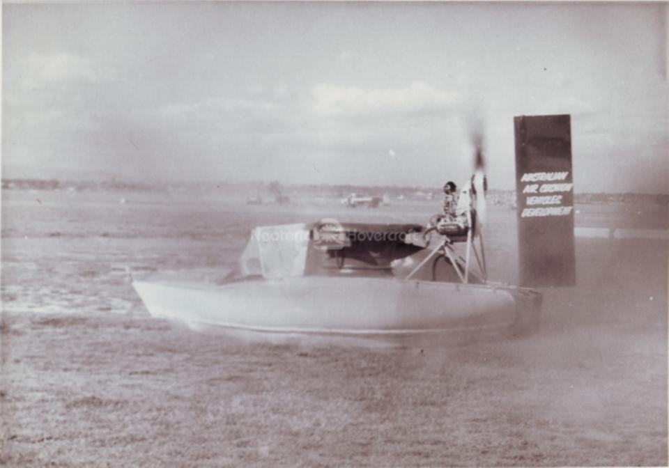
Fig. 14b: High Speed Demo Run at Moorabbin Airport close to Melbourne. Demo was to show the 50 companies the result of their contributions. | ||||
A further public demonstration at Moorabbin Airport showed the effectiveness of the craft operating on the unprepared verges of aircraft runways. See photo 14b.
Trials over a farmer's unprepared grass field and adjoining Lake Colac showed the advantages of a relatively large lift air supply and ample thrust in rough conditions. Also demonstrated was the need to allow for adequate stopping distances when no reverse thrust is available and skidding on wet grass is the only means of braking?
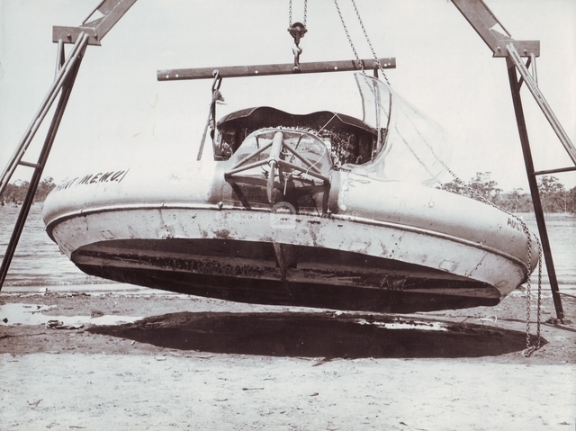
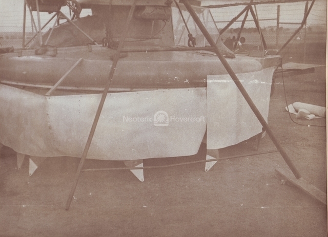
Trials at Bacchus Marsh on a standby airstrip presented the opportunity to determine the top speed potential of the AACVD5 on dry flat ground. Instrumentation installed included a calibrated anemometer and aircraft type data recorder. On long flat gravel runways and verges, speeds up to 55 feet per second (38 mph) were measured. Fig. 15 is a photograph taken at this time. At the end of this trial period the first deep skirt was fitted (Fig. 16a). Because of the trim implications of the extended bow section, squaring off the stern with a tubing structure covered with fabric. This additional lift area provided a balancing cushion area at the stern. The design was a basic 'C-skirt' configuration with supporting fabric diaphragms fastened back to the base structure (Fig. 16b). Although the 2 foot ground clearance obtained was impressive, stability was poor and the craft unusable in that state.
 |  |
 |
|||
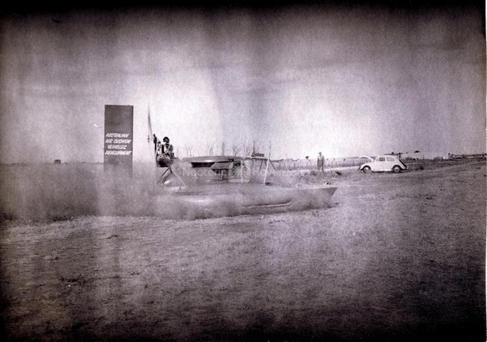
| Fig. 15: Speed Trials at Bacchus Marsh Airport (near Melbourne) in extremely dusty conditions. | Fig. 16a: Fitting the fifth 2-foot-deep flexible skirt at the Bacchus Marsh Airport. | Fig. 16b: Equipped with a 2-foot-deep air cushion, the craft was controlled via a large rudder and a bow-mounted McCulloch drone motor thruster. The rear thruster is a 1200cc VW engine. | |||
To obtain a more stable cushion, the bow was rounded off via a tubular structure bent in a semi-circle and braced back to the existing bow structure. The side and rear sections of the 'C-skirt' were pressurized by adding an inner wall, this being attached to the diaphragms. The top edge of this wall was left open to allow passage of air into the cushion.
Trials were held at Lake Modewarre outside of Colac in Victoria to check the performance of the 2-foot-deep skirts over water. Also, obstacle performance of the craft was found to be improved with the increased cushion depth, but drag was higher and maneuverability much impaired.
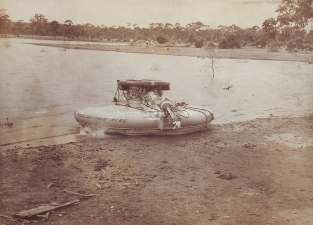
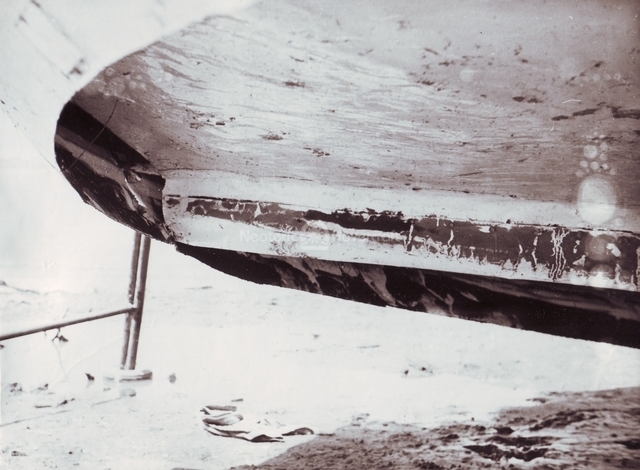
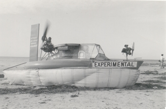
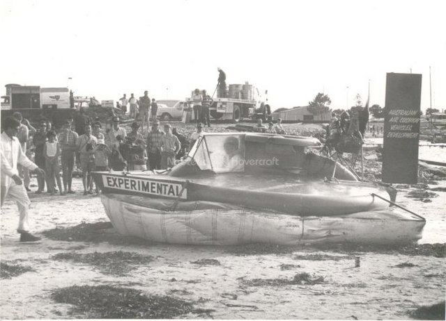
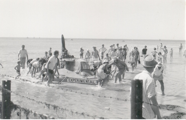
A bag-type longitudinal stability skirt was fitted with inflation from the plenum near the fan. A bow thruster unit using a 2-cycle, 2-cylinder McCulloch drone engine, driving a small propeller and mounted on a rotatable pylon, was fitted to aid maneuverability. The craft was transported by road to the first Australian Hovercraft Conference at Adelaide and demonstrated over beach and shallow water (see Fig. 17a). A massive skirt tuck-under and plough-in ended the demonstration. Fig. 17b was photographed at that event. The bow thruster was found to be effective when operational but extreme engine unreliability limited its use to a few very brief tests.
 |  |
|||||
| Fig. 17a: The AACVD5 makes its second public appearance in 1968 at the 1st Australian Hovercraft Conference, sponsored by the South Australian Branch of the Royal Aeronautical Society in Adelaide. In the picture, the craft is equipped with a single blade swiveling propeller bow-thruster, driven by a McCulloch 2-cylinder 2-cycle aircraft drone engine. | Fig. 17b: The accident Peter Crew, Head Mathematician from the British Hovercraft Corporation in the UK, witnessed the accident that befell the AACVD5 and explained it as a classic skirt tuck-under and plough in. The craft suffered damage and was helped ashore by an enthusiastic public. |
|||||
| Company History | |