The Chris Wayman's Hovercraft Story
1. Collecting Hovercraft from Felixtowe
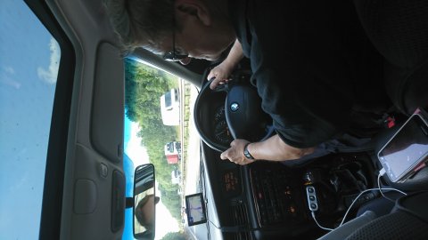
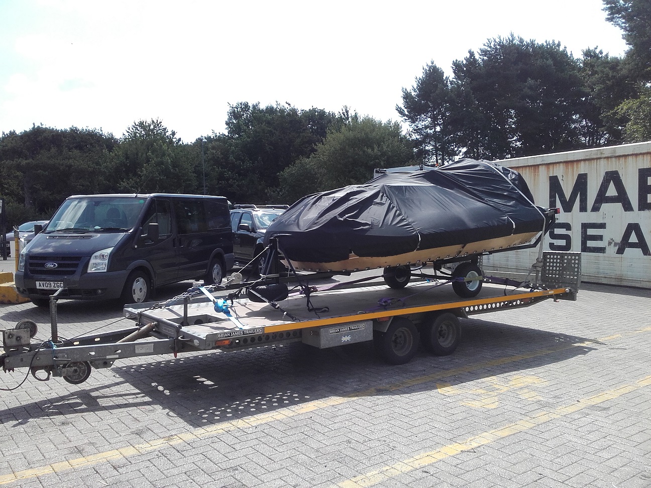
Driving to fetch Hovercraft
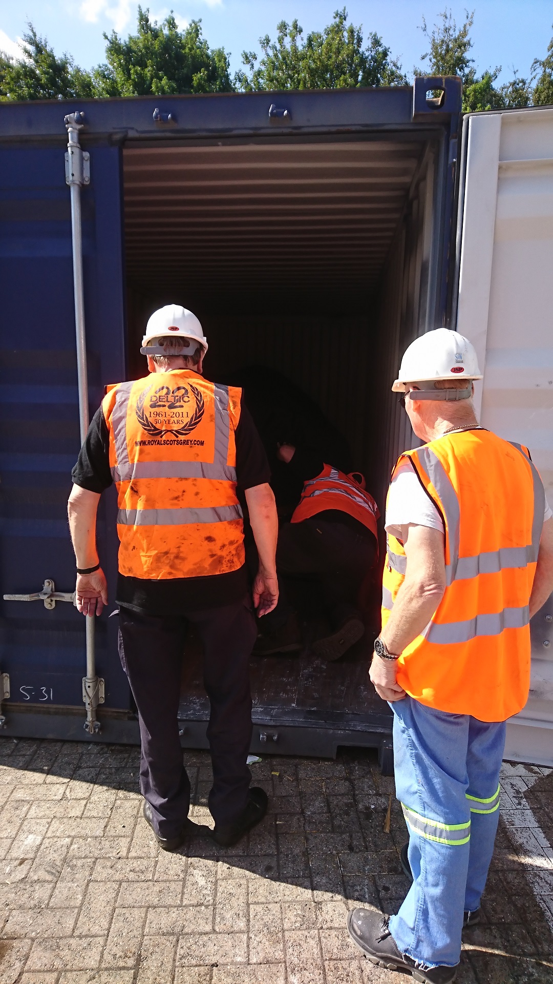
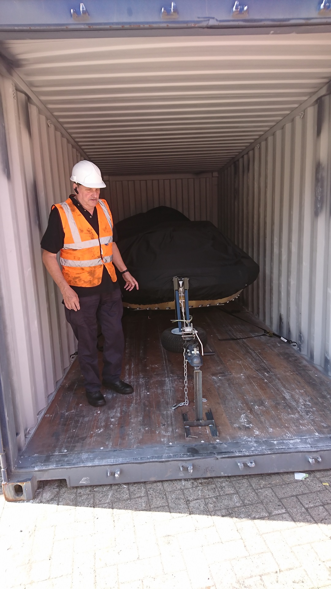
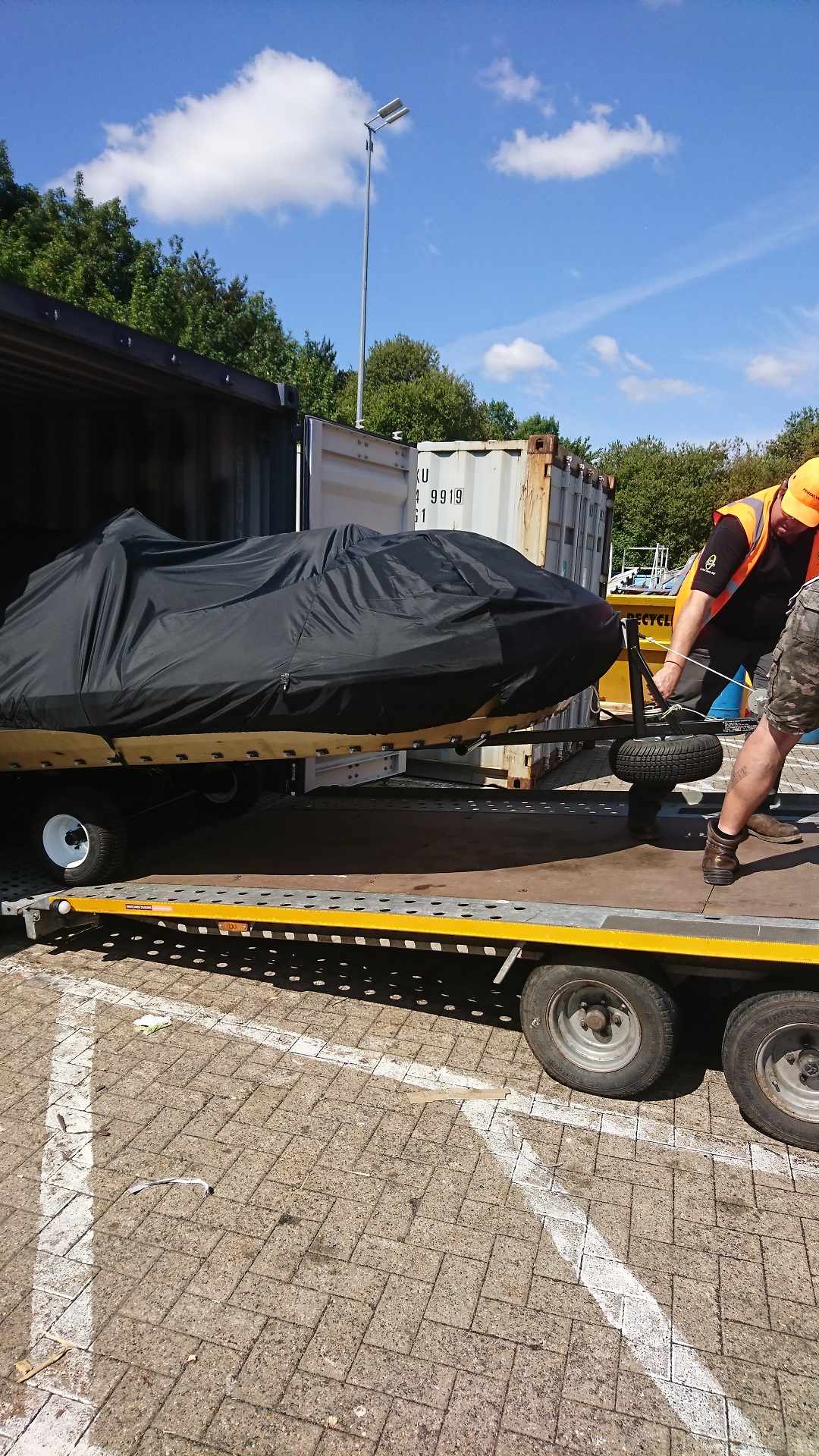
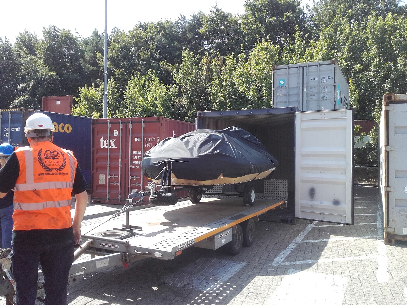
First view inside container. First opening since it left Neoteric
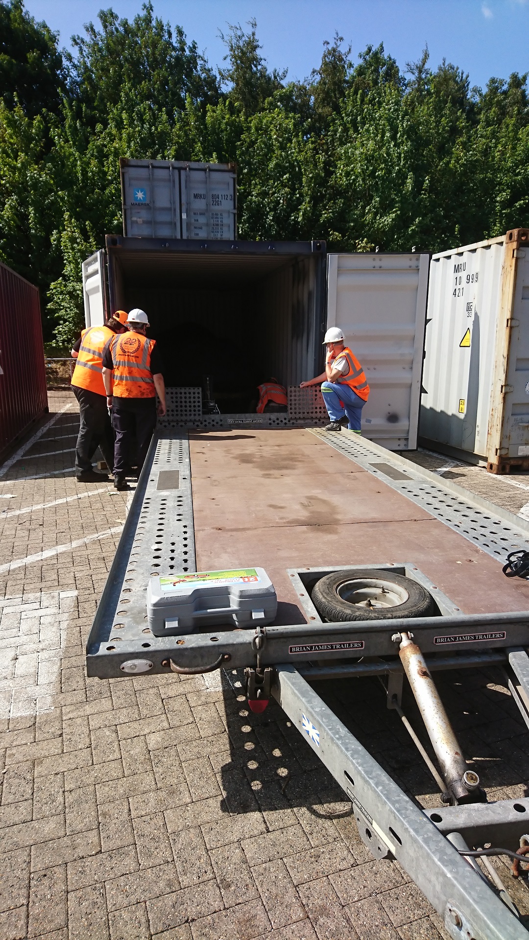
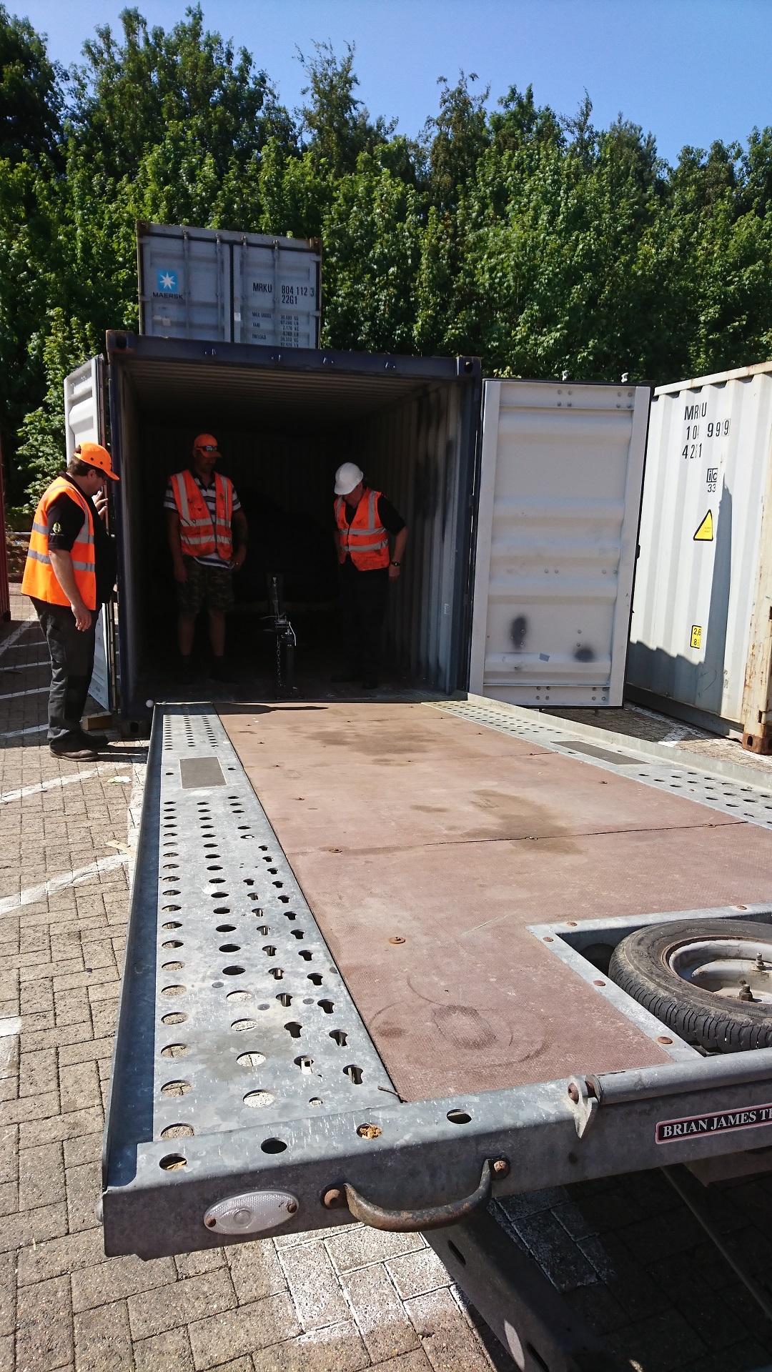
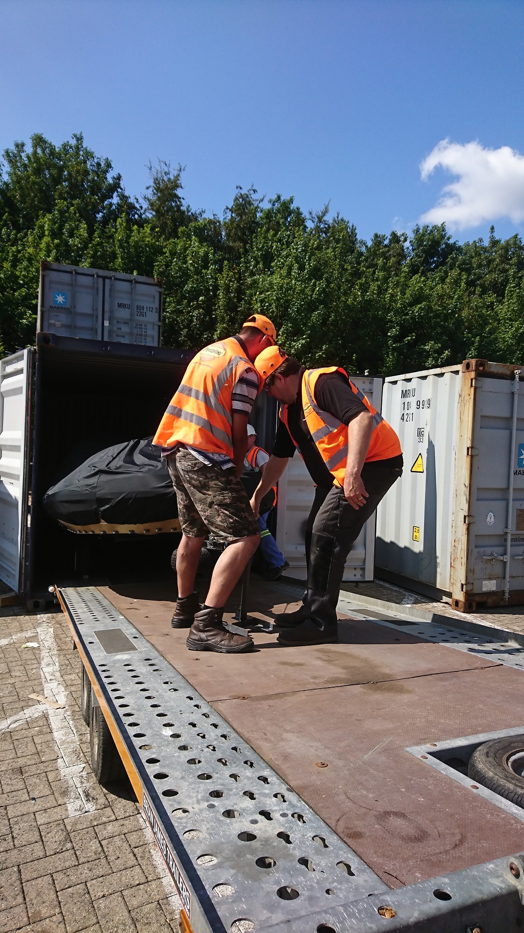
Trailer backed up to container
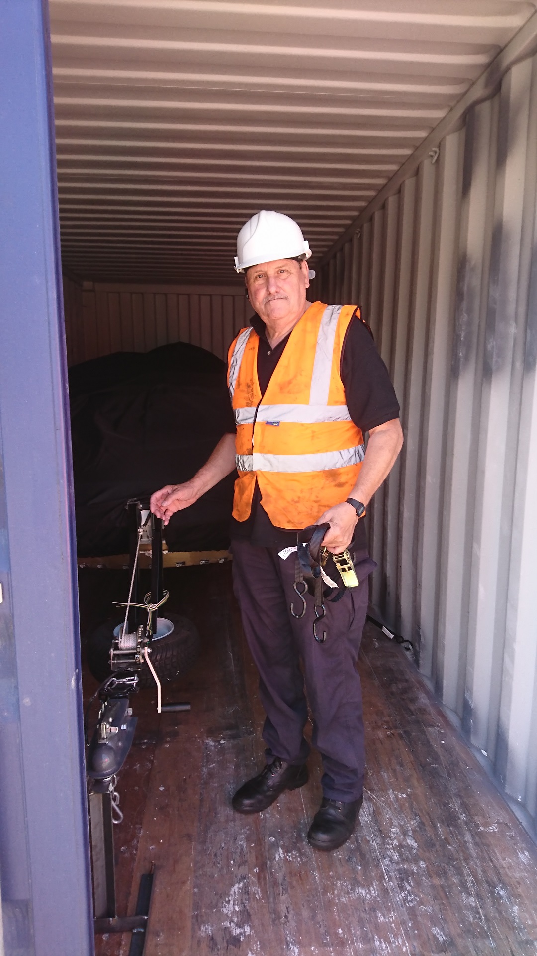
Trailer now aligned for loading
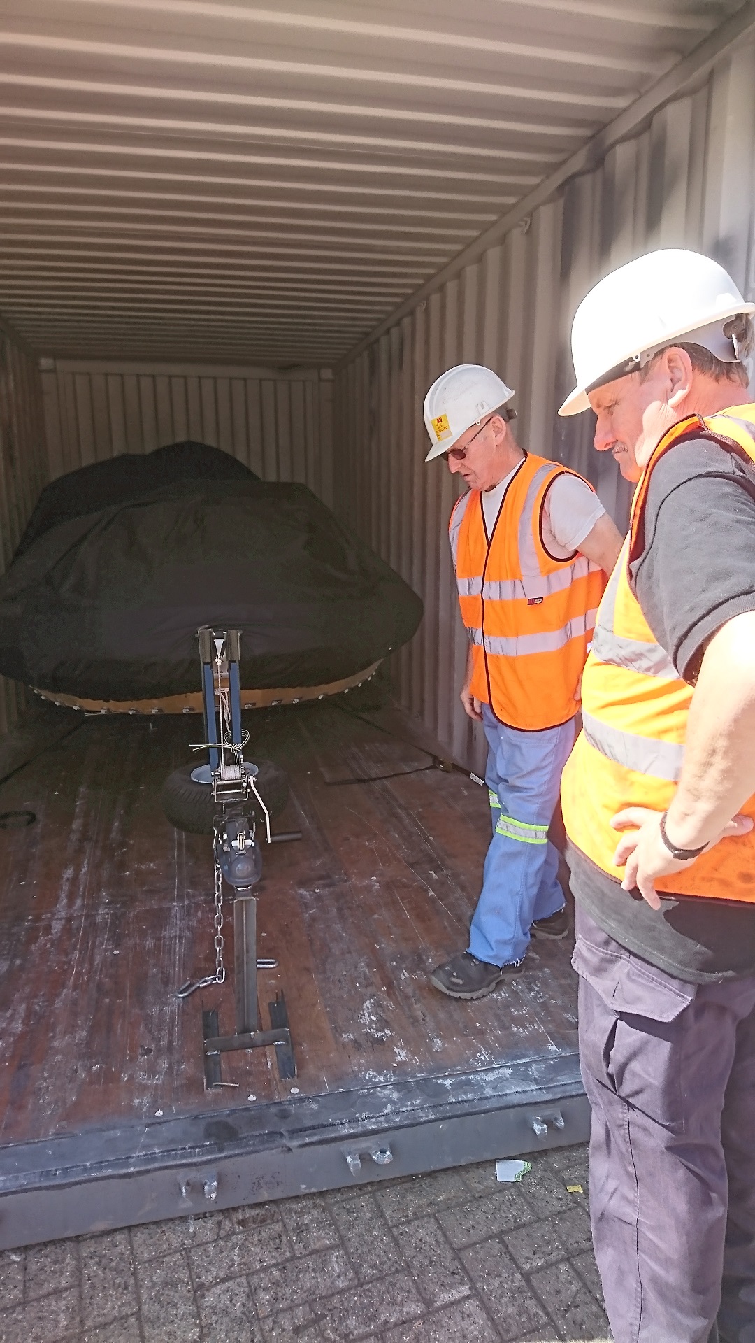
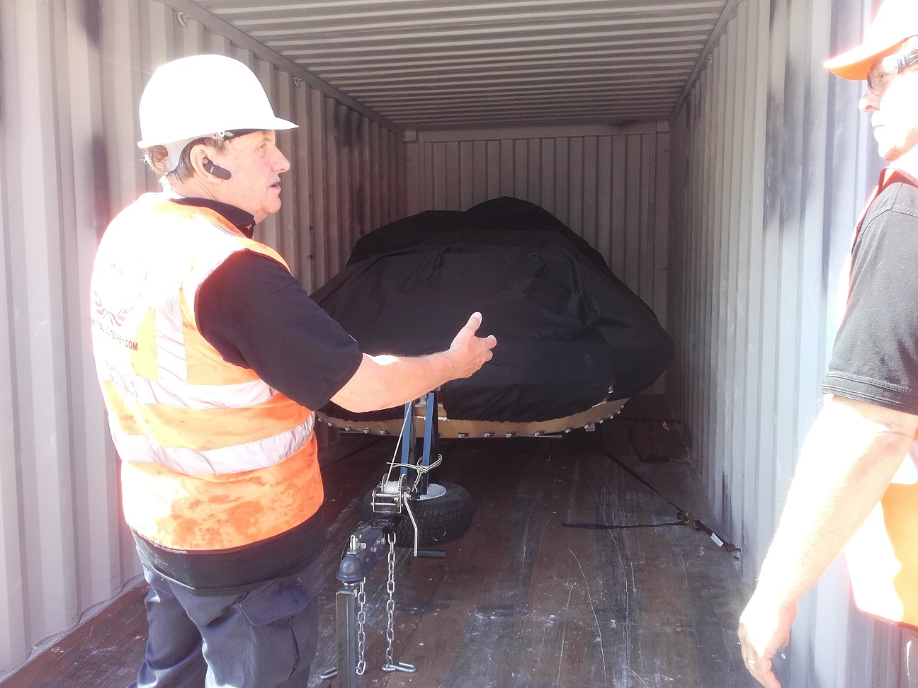
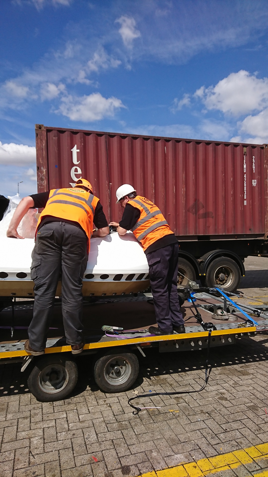
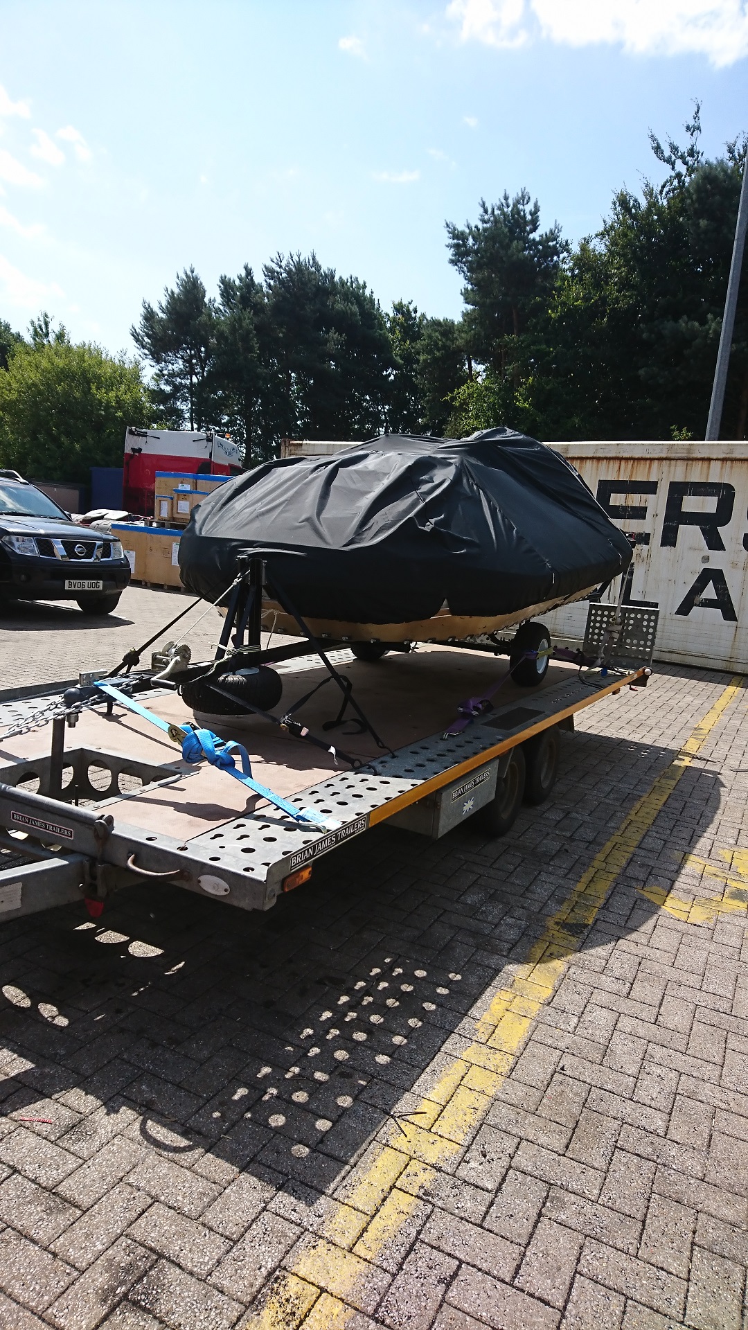
Checking where its safe to rope down
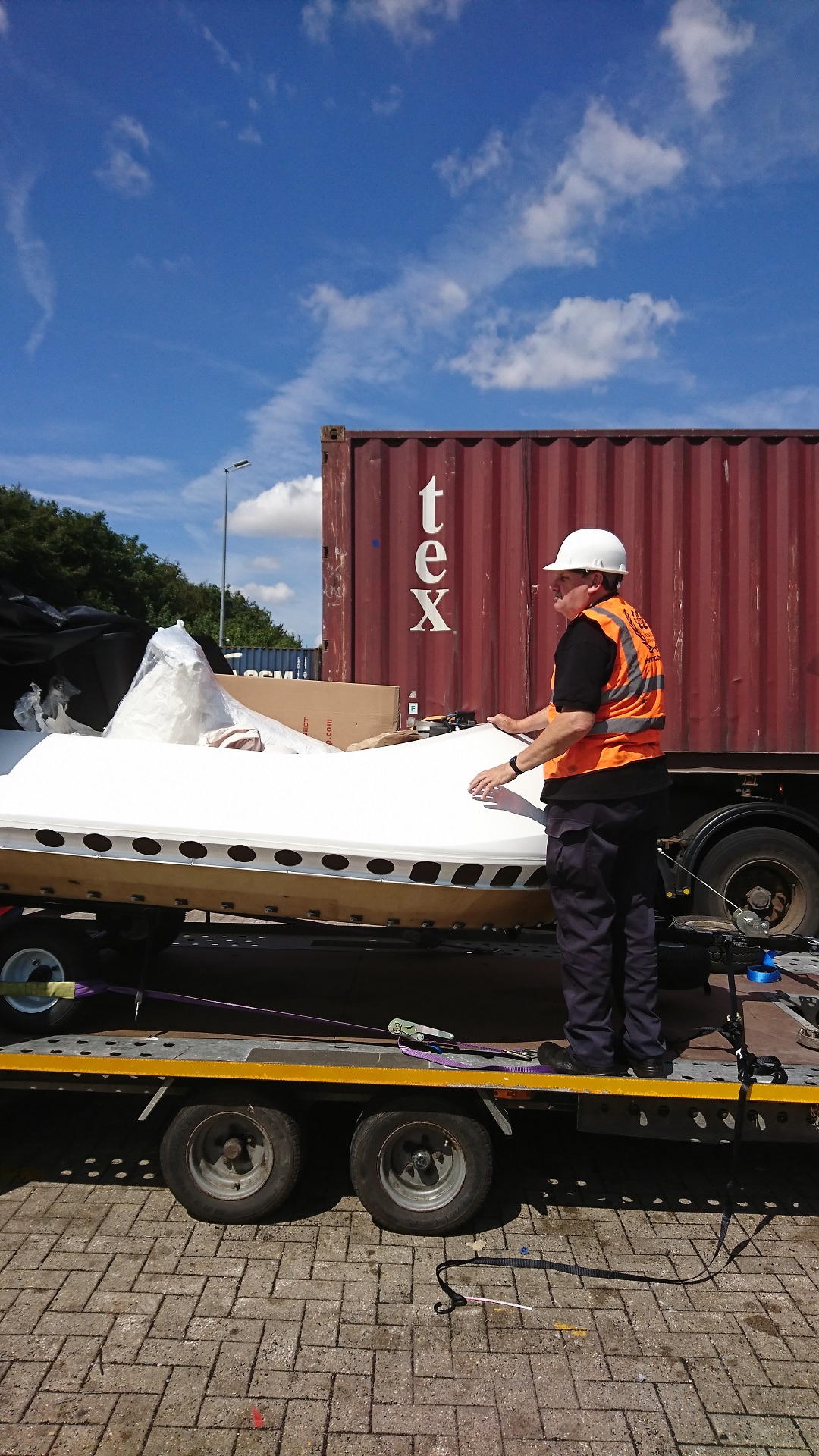
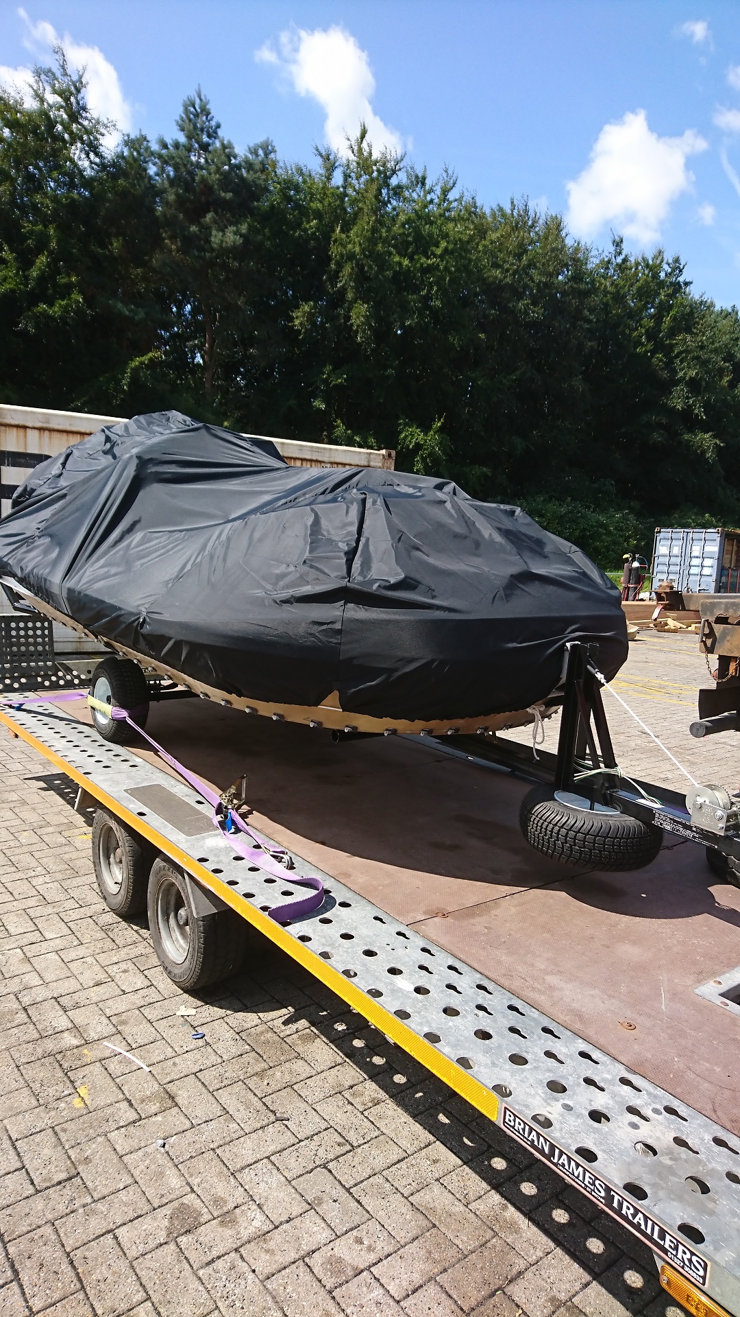
Final rope down, ready to go
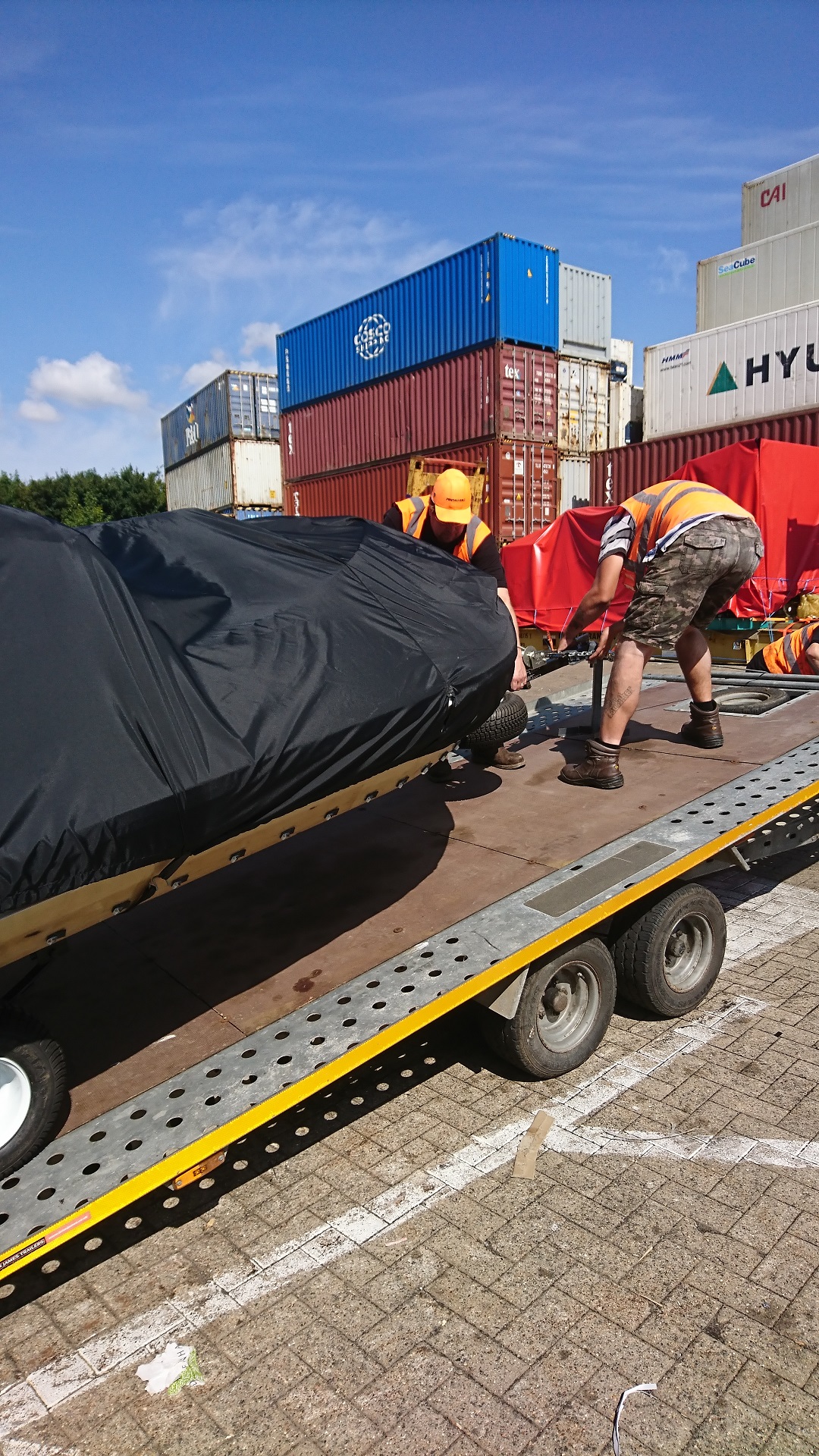
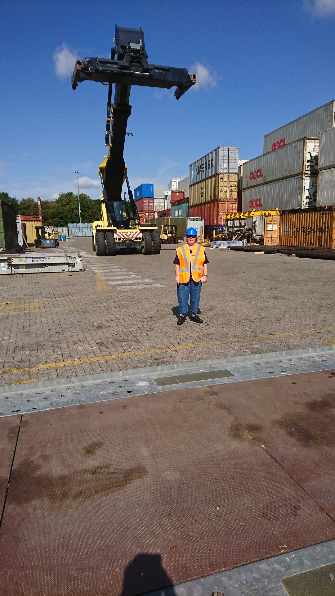
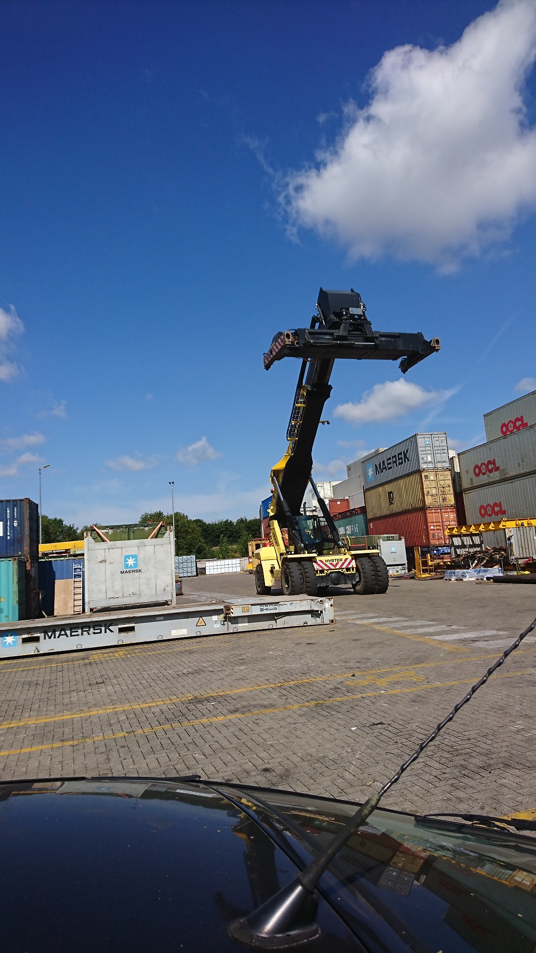
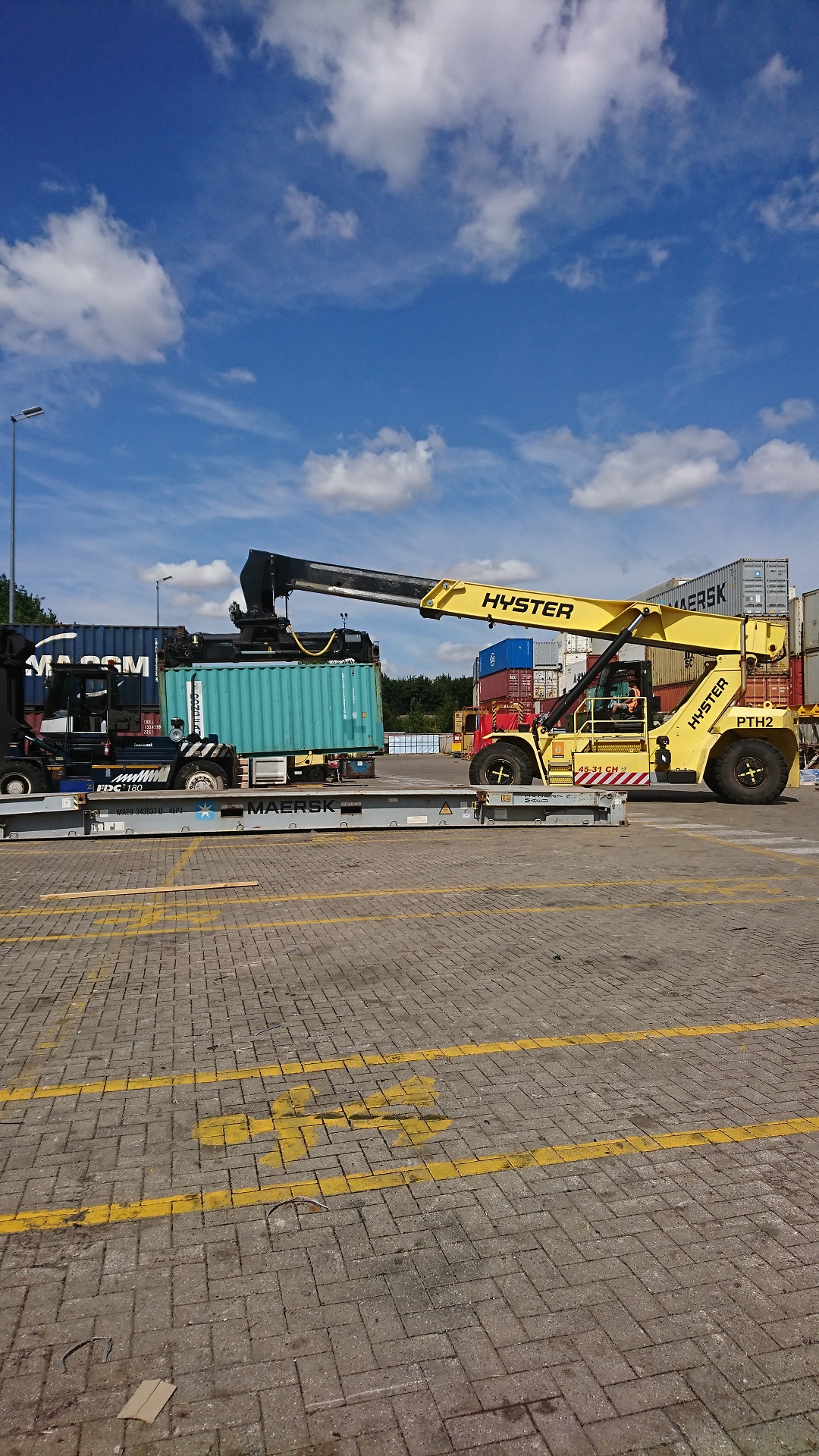
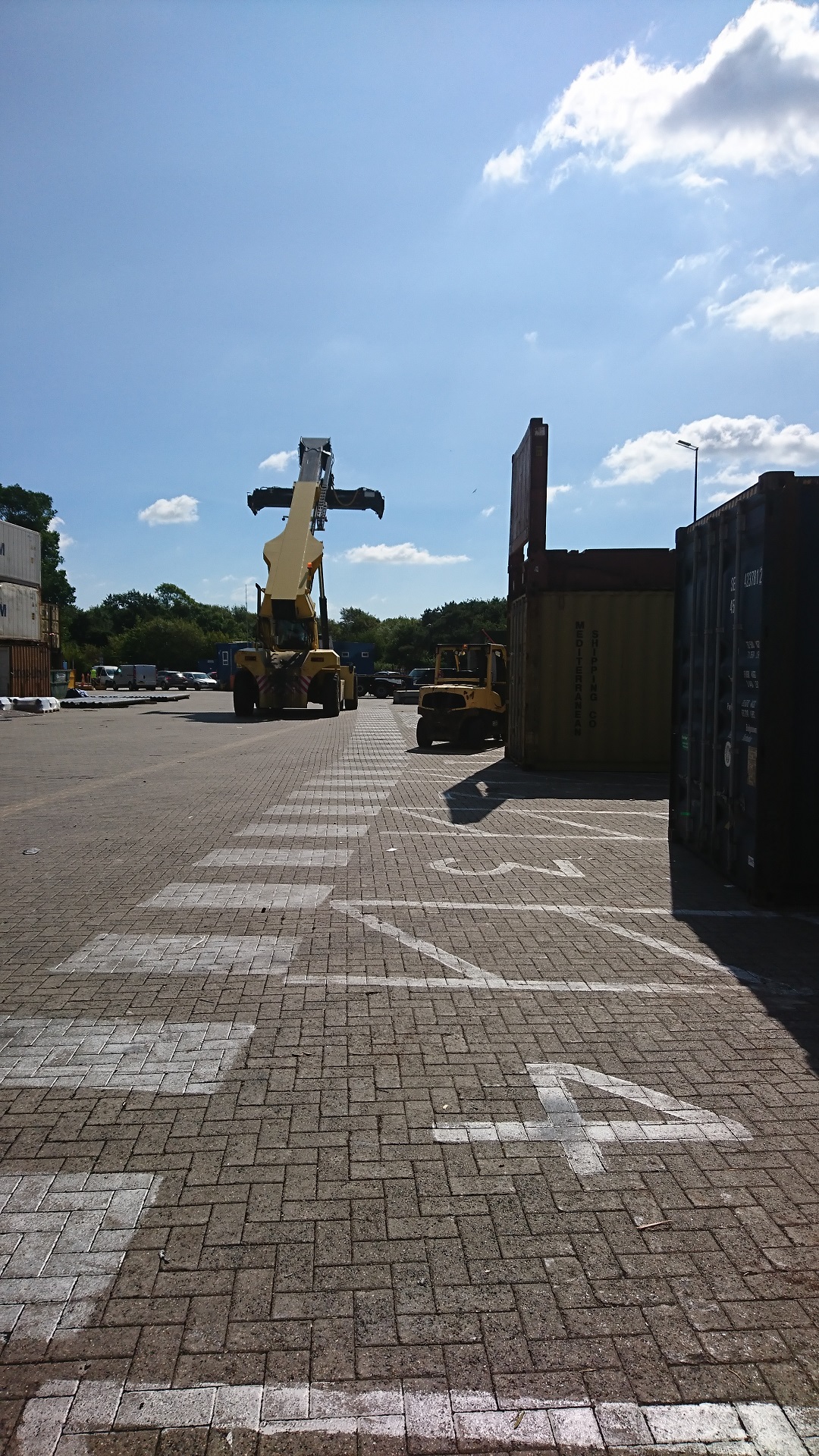
Some serious pieces of kit at the Docks
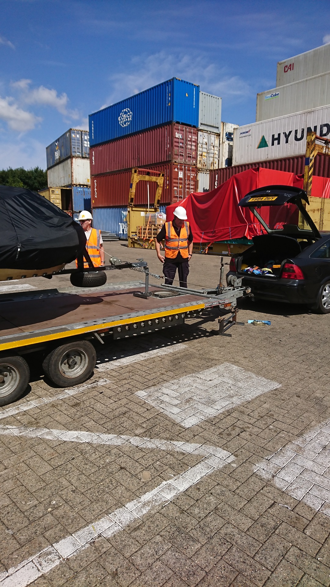
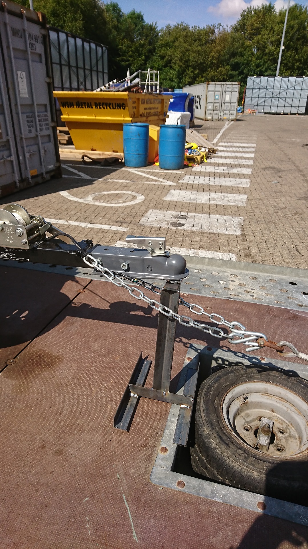
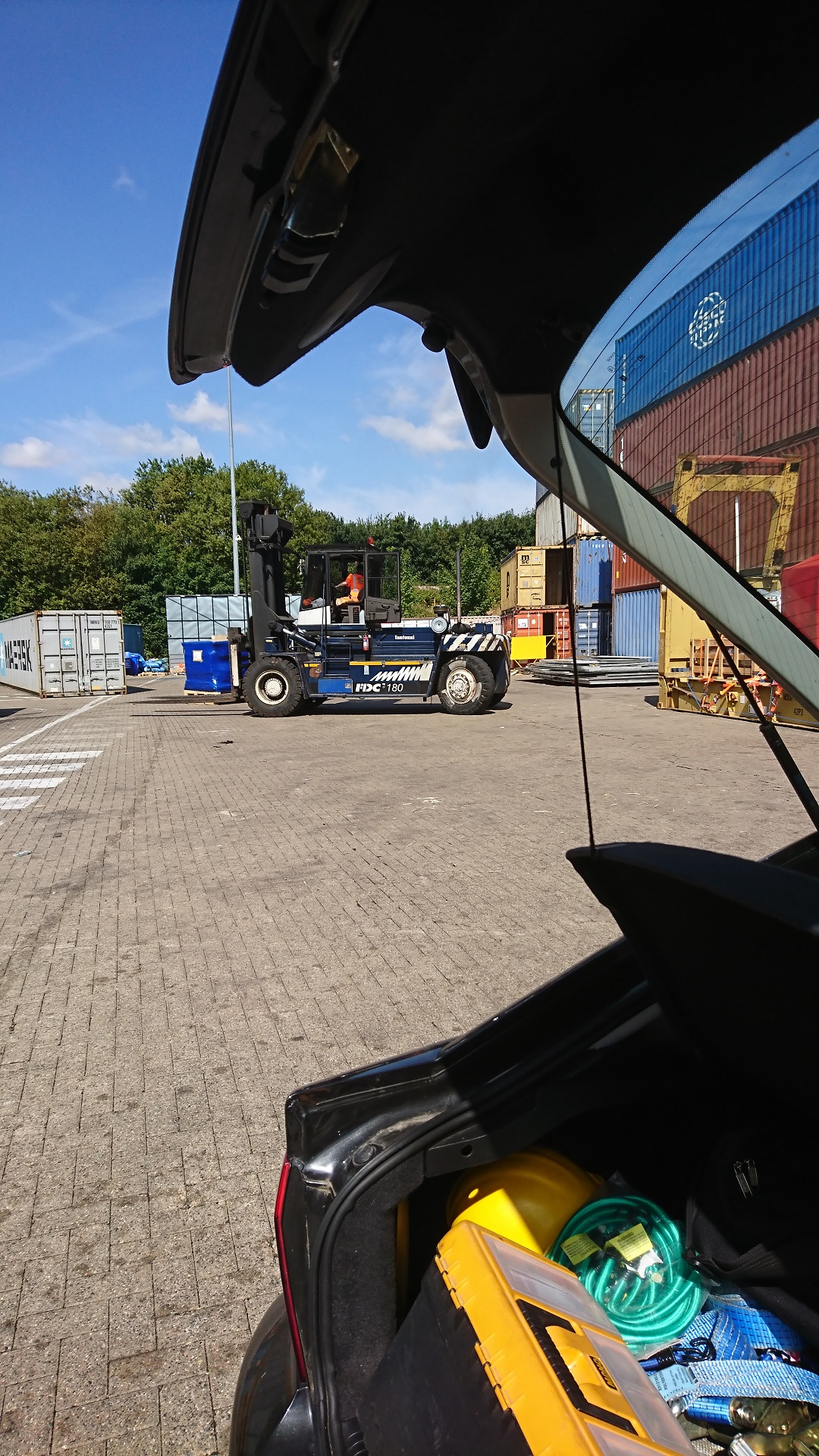
Not a good area for Vectra + Trailer
Very busy area, not Vectra friendly
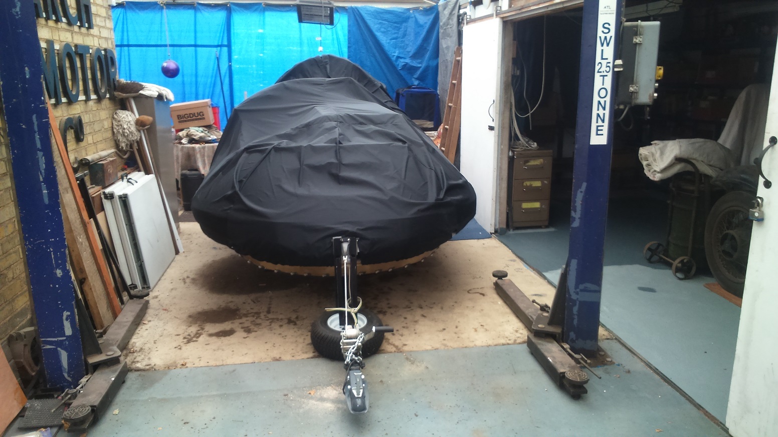
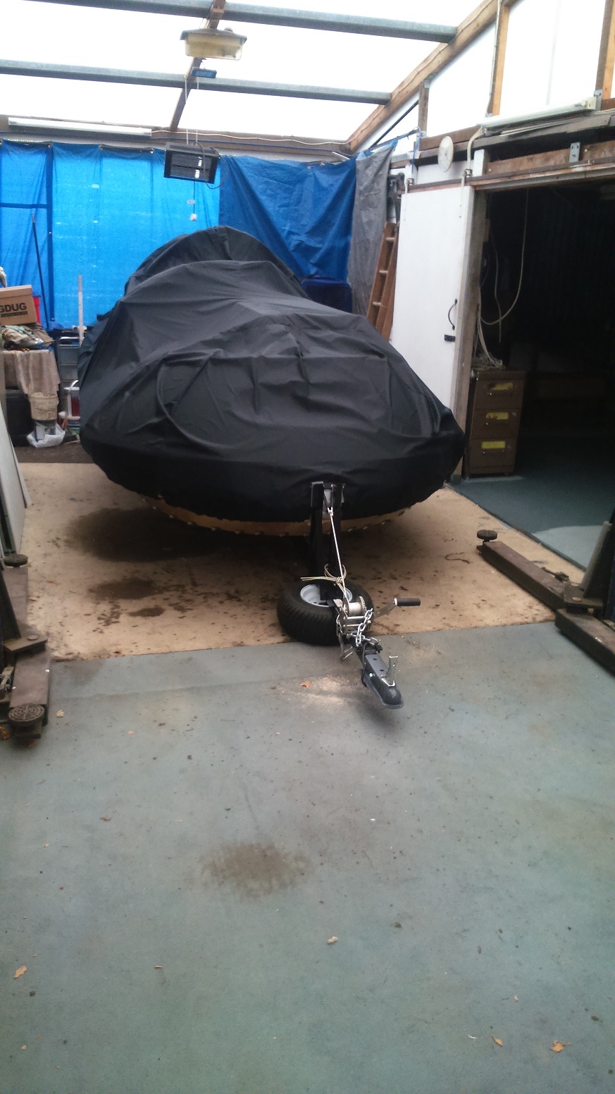
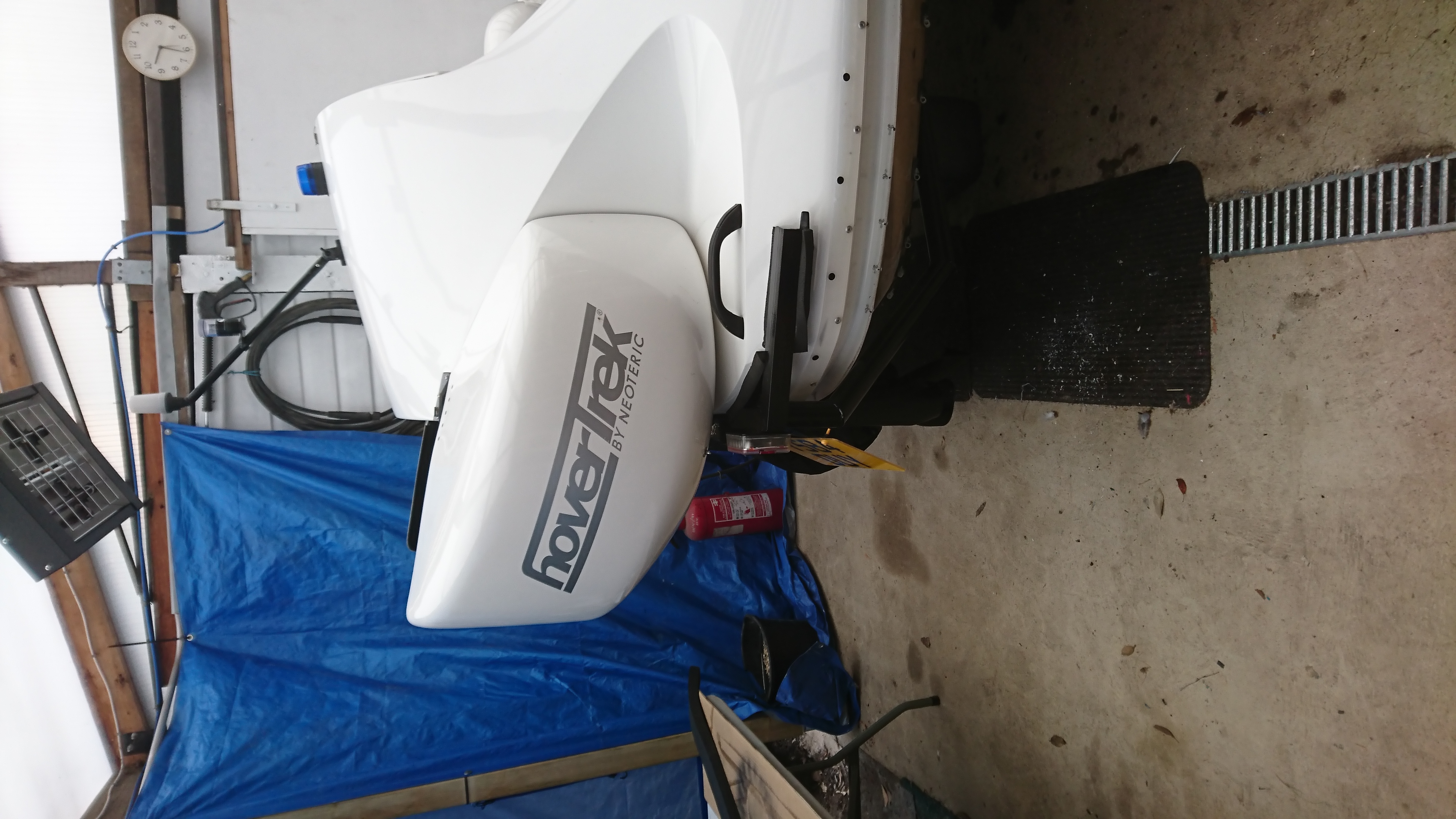
Home at March in Lift Shed
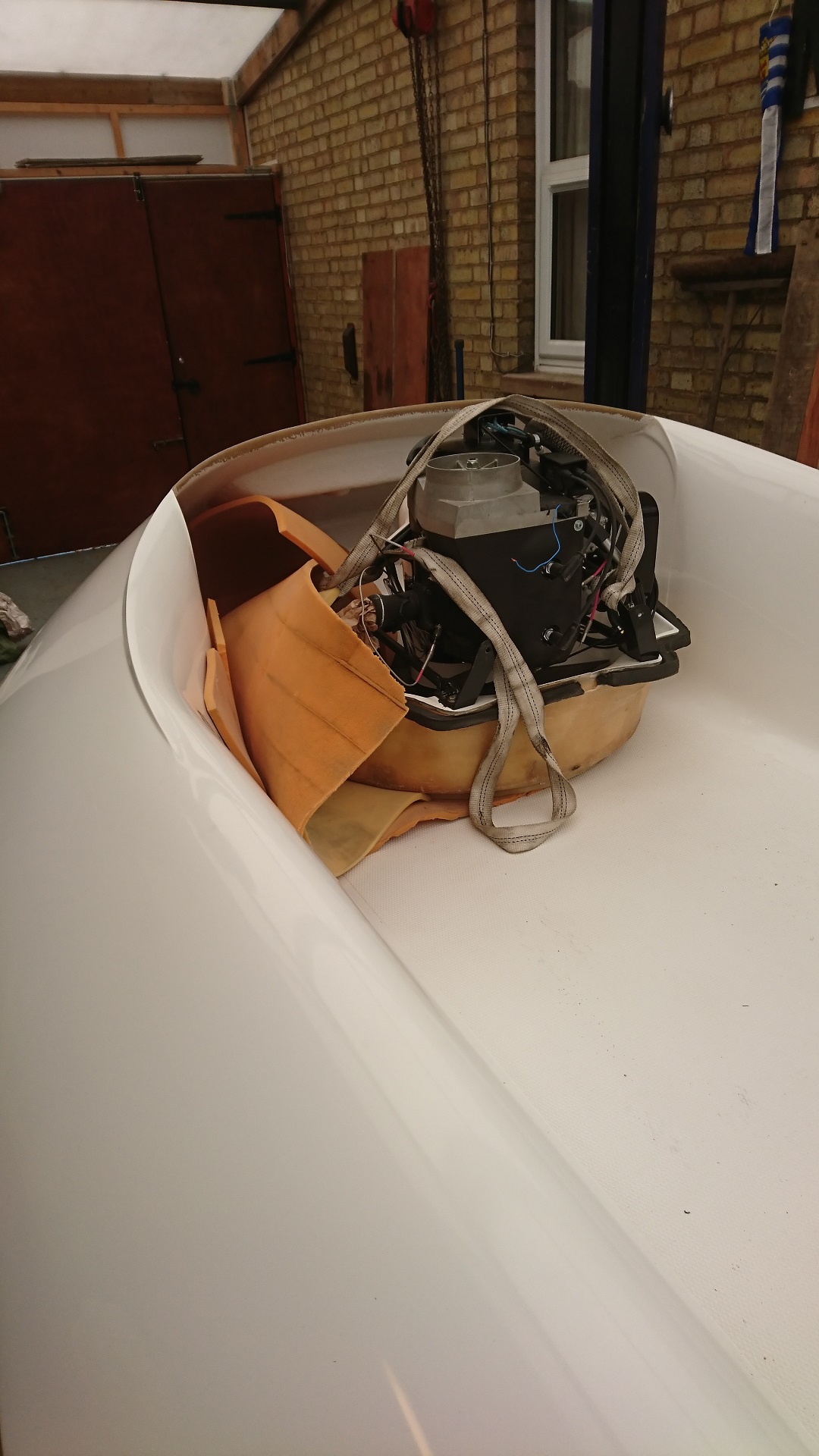
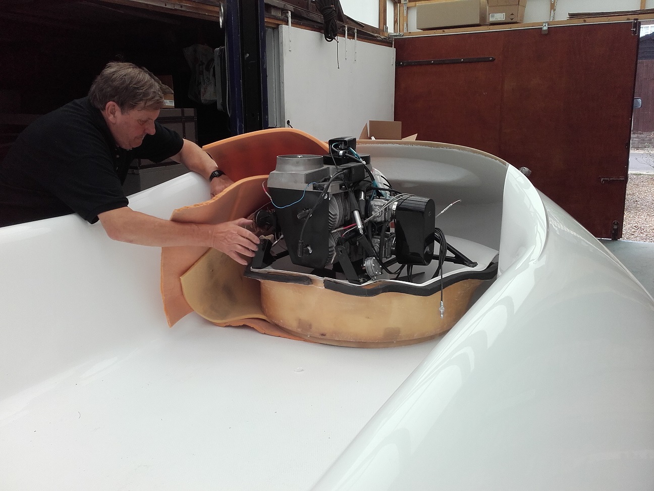
Power unit about to be slid out
Sliding out the power unit
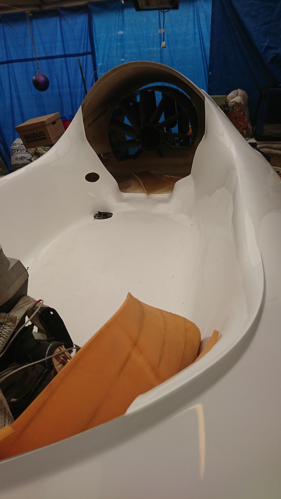
Almost completely unpacked
Parts stored awaiting fitting
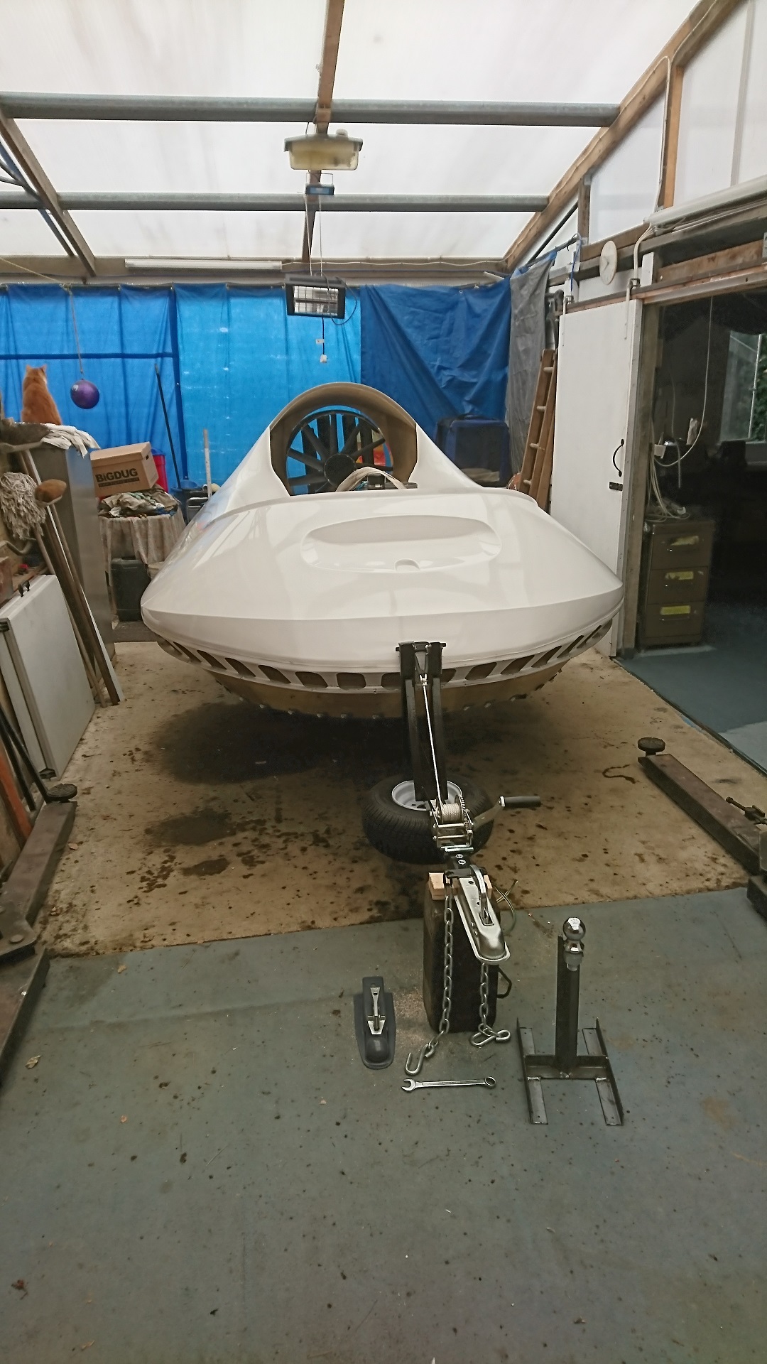
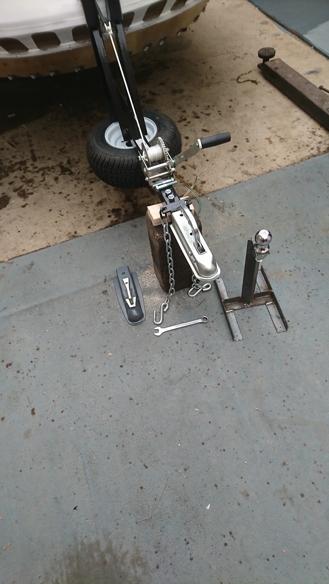
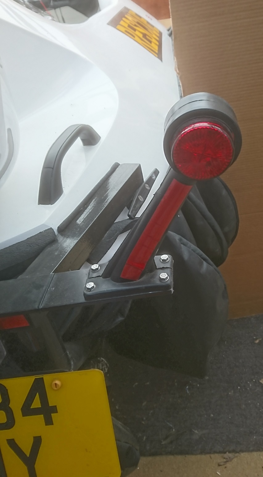
3. Towing Equipment
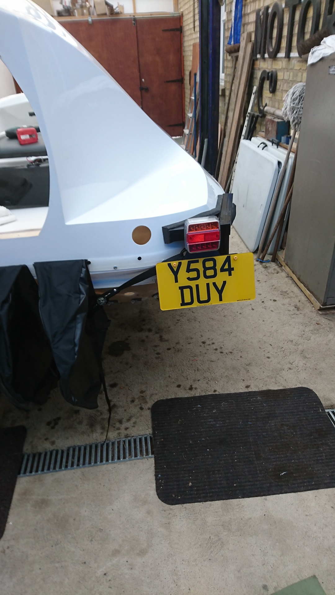
This was changed to UK/European 50mm hitch and new rear LED light clusters fitted with modified wiring for 7-pin UK/European plug and socket.
Changing the towing equipment
UK and European towing hitch mod
New rear lights and number plate
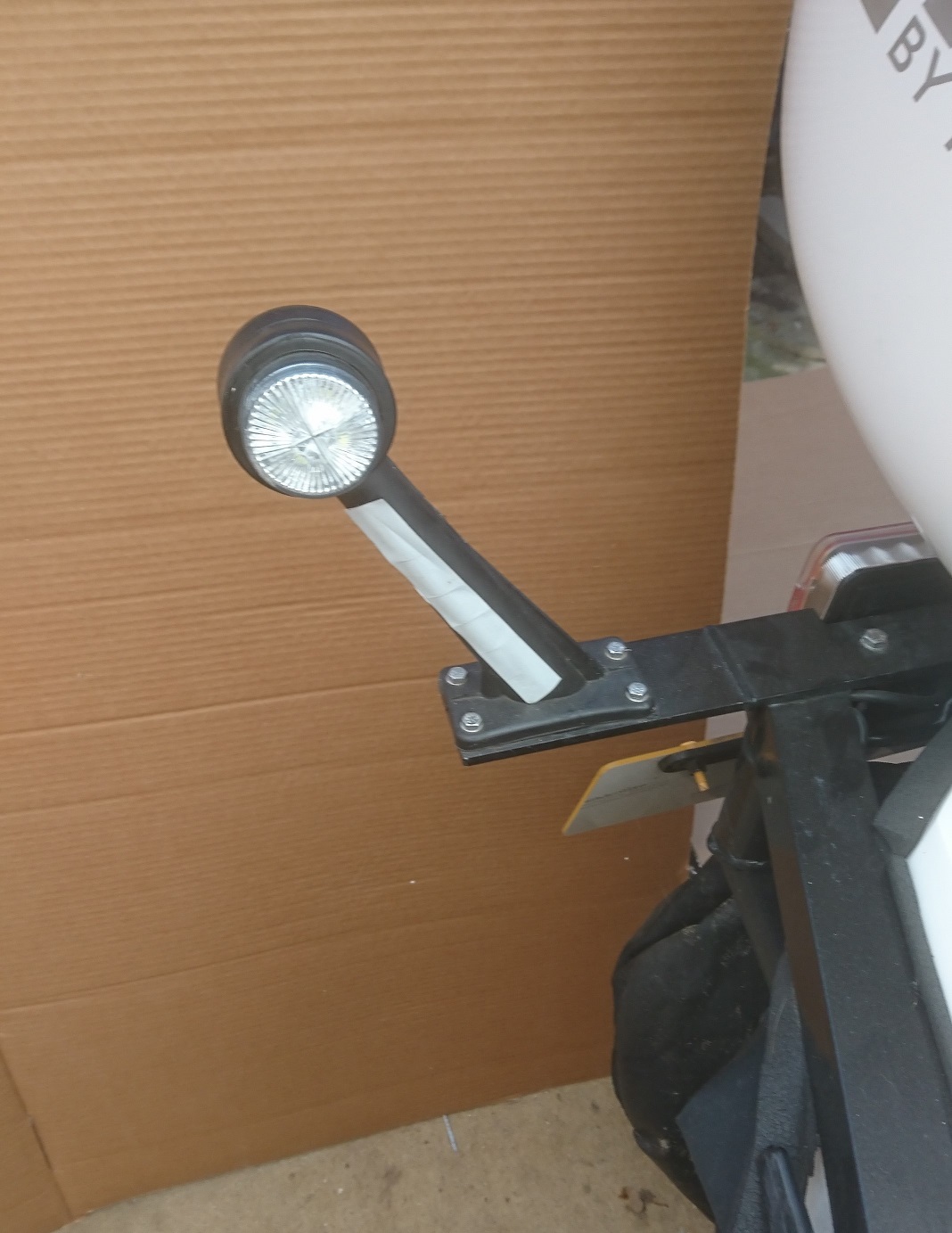
We extended the rear arms with a 6'' piece of angle and bolted these LED Marker lights on, wired in with the rear lights
Front view, makes a lot of difference when towing at night. You can see where you are and other people can see you too. Much safer
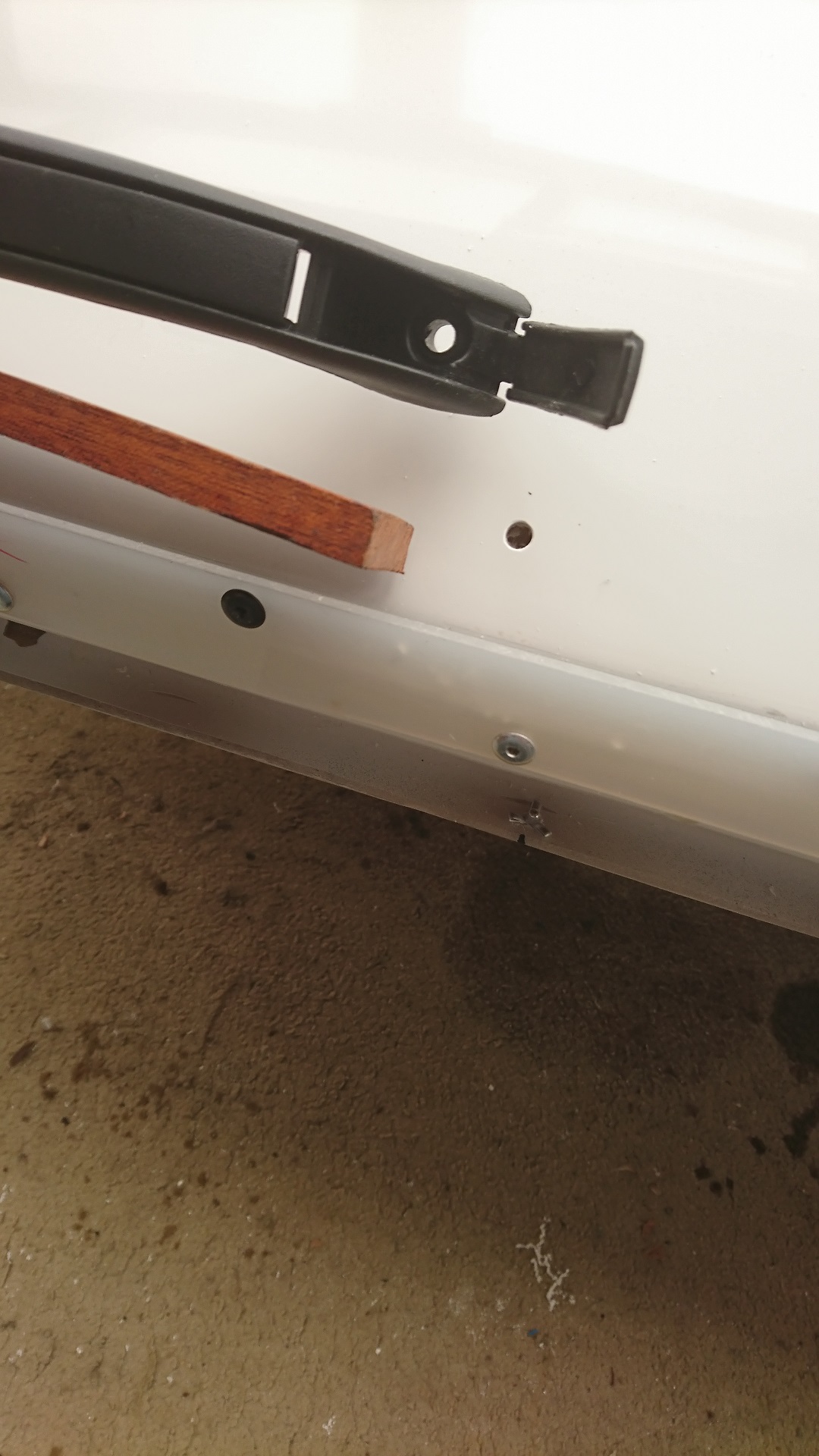
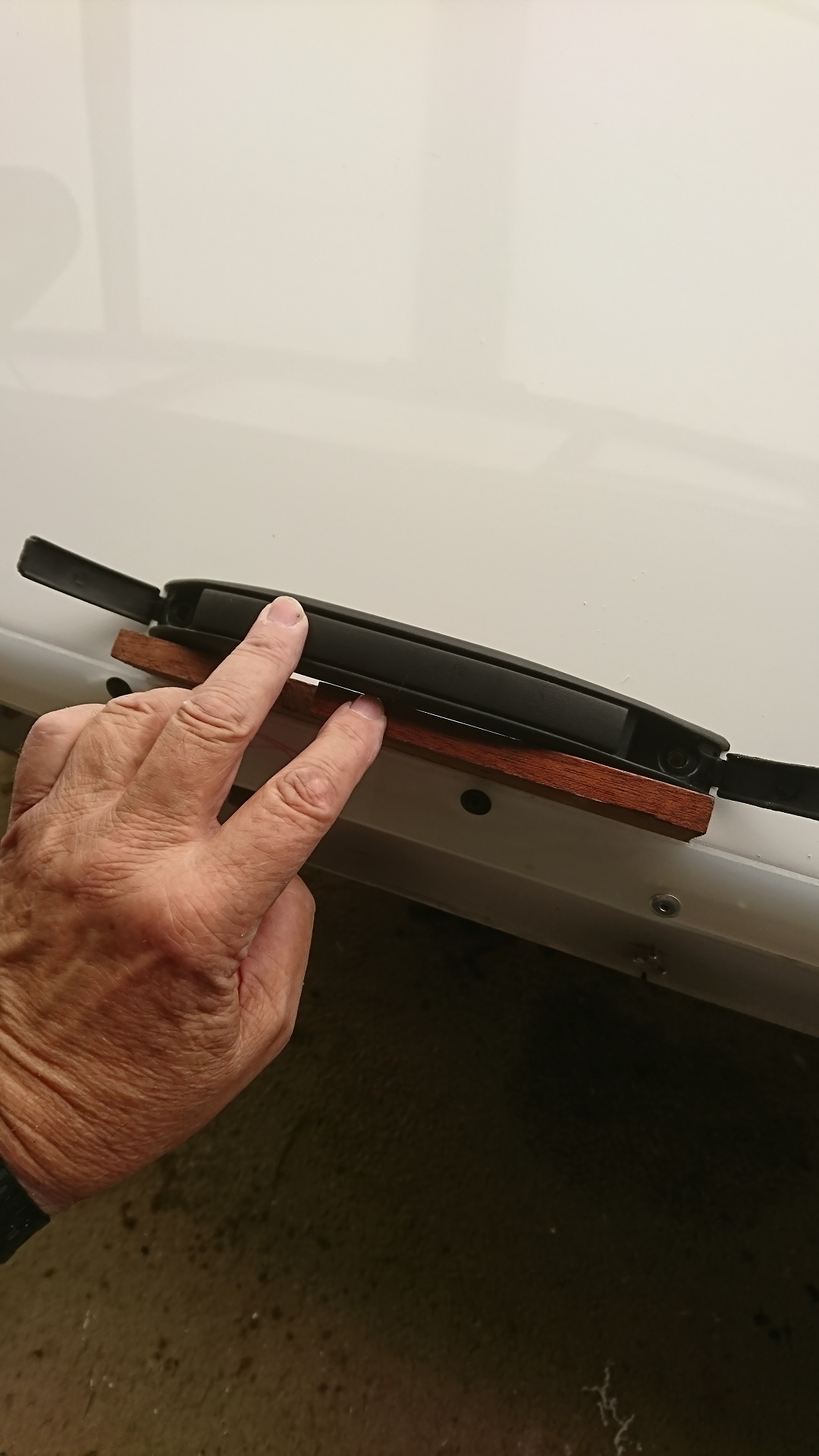
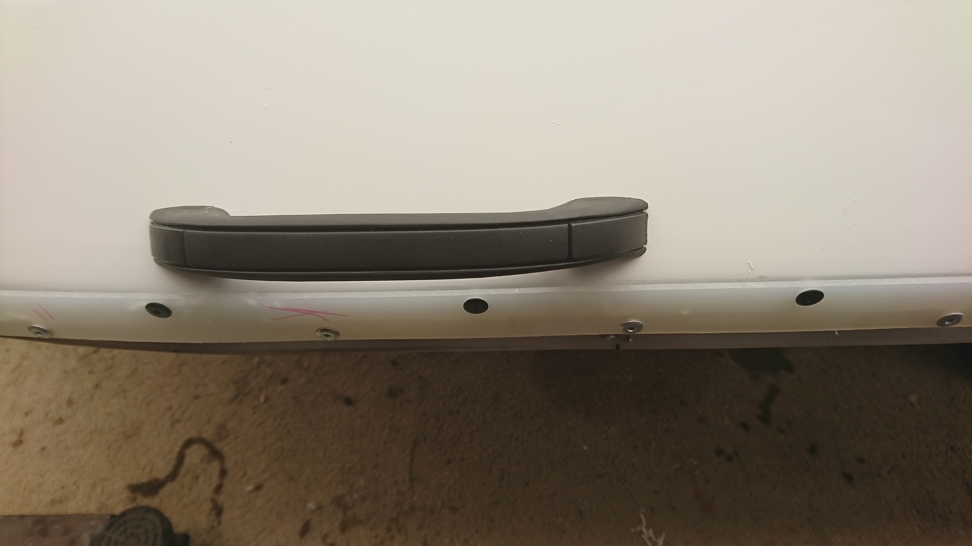
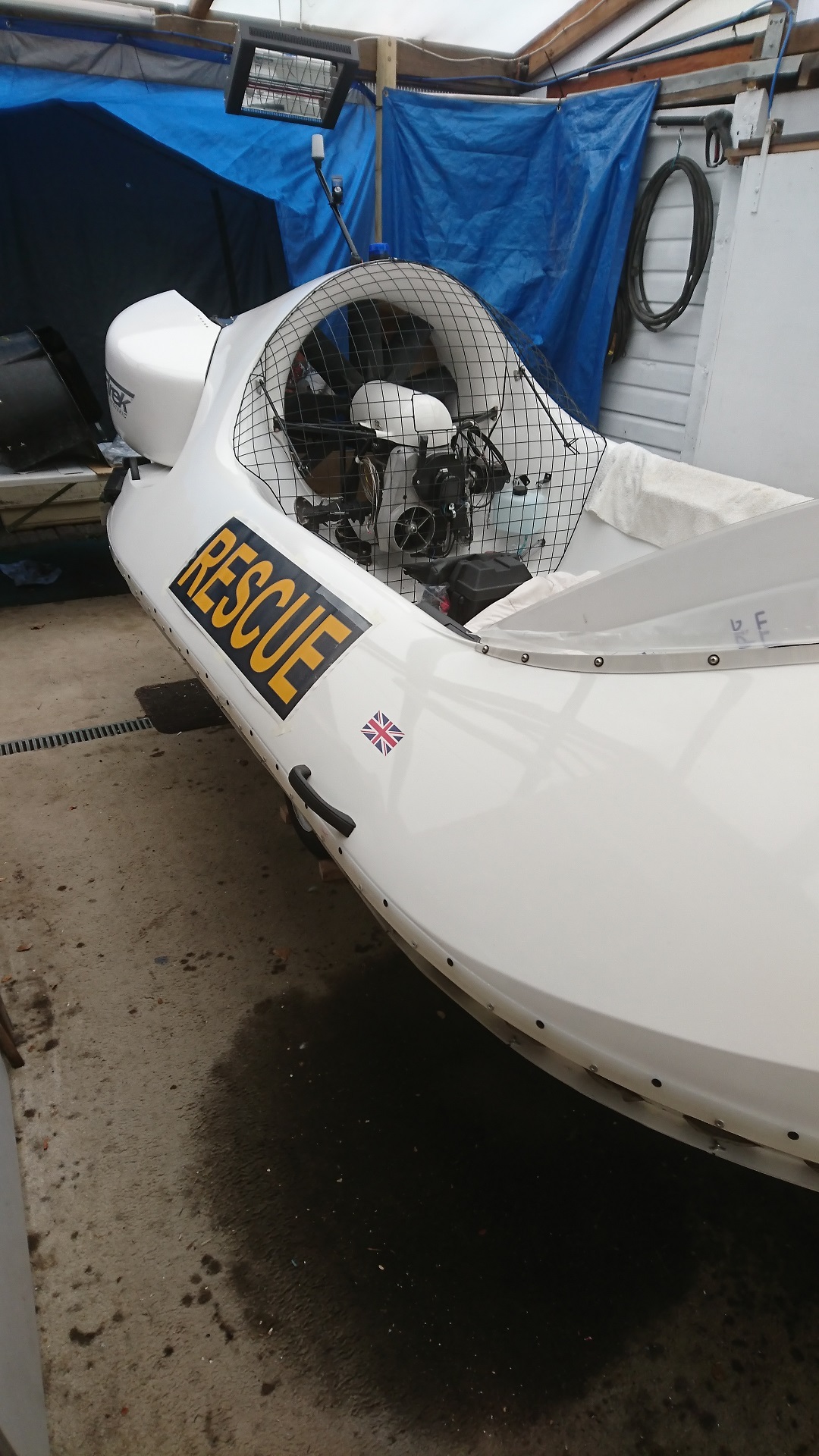
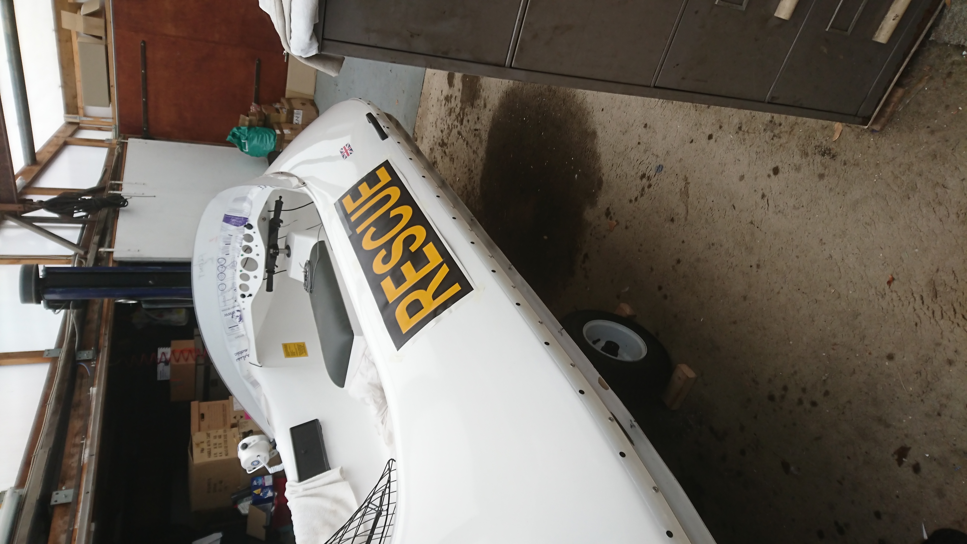
4. Skirt Rail and Rescue Lift Handles
Just in time we found out black rivets to top of the rail, silver rivets on the lower part of the rail. Didn't find that in the instructions!
11mm piece of wood used as spacer from skirt rail to Rescue Lift Handle
Using piece of wood to space Rescue Lift Handle
Rescue Lift Handle just been drilled
Rescue Lift Handle finished,both front Handles same distance from skirt rail
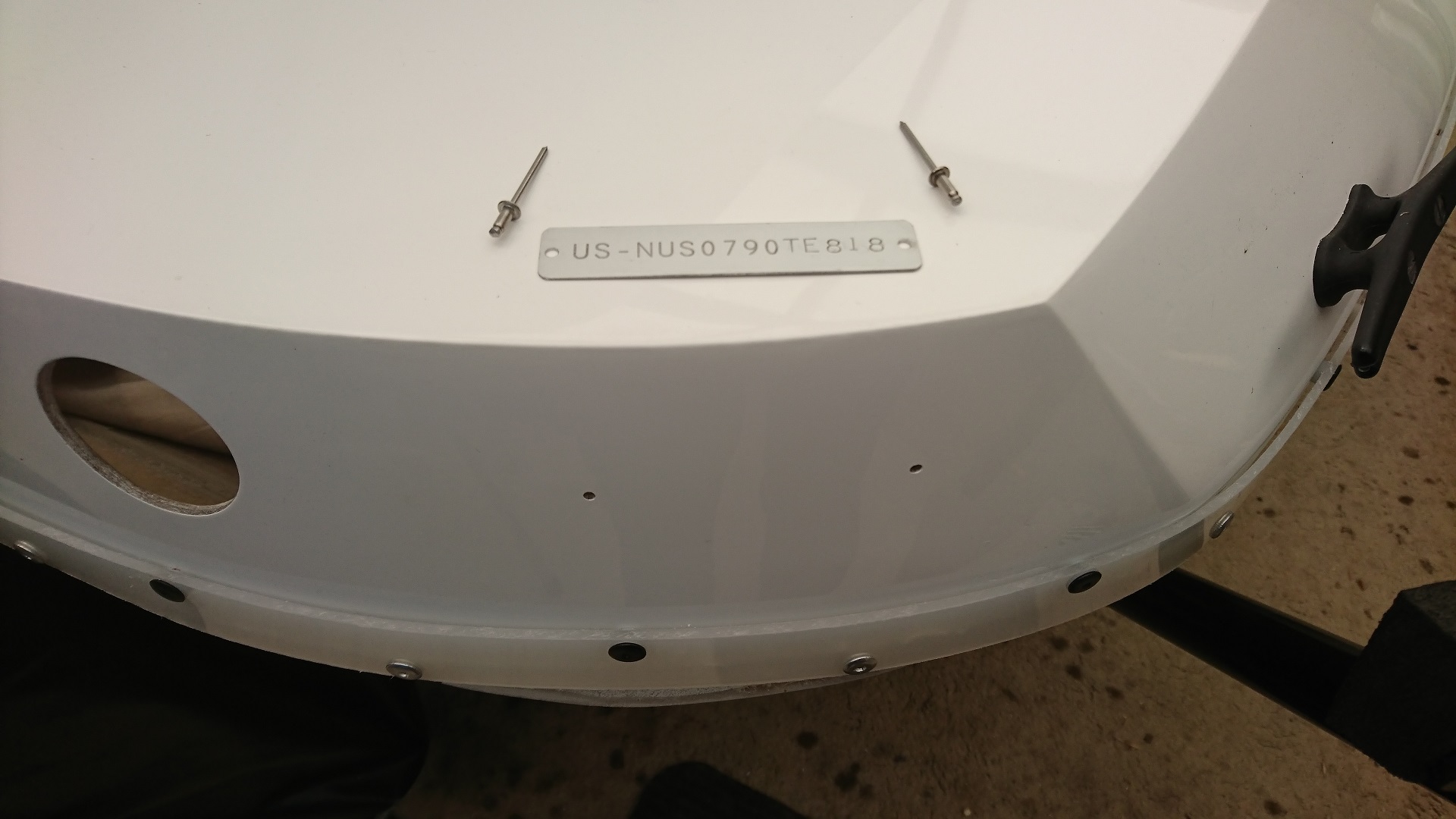
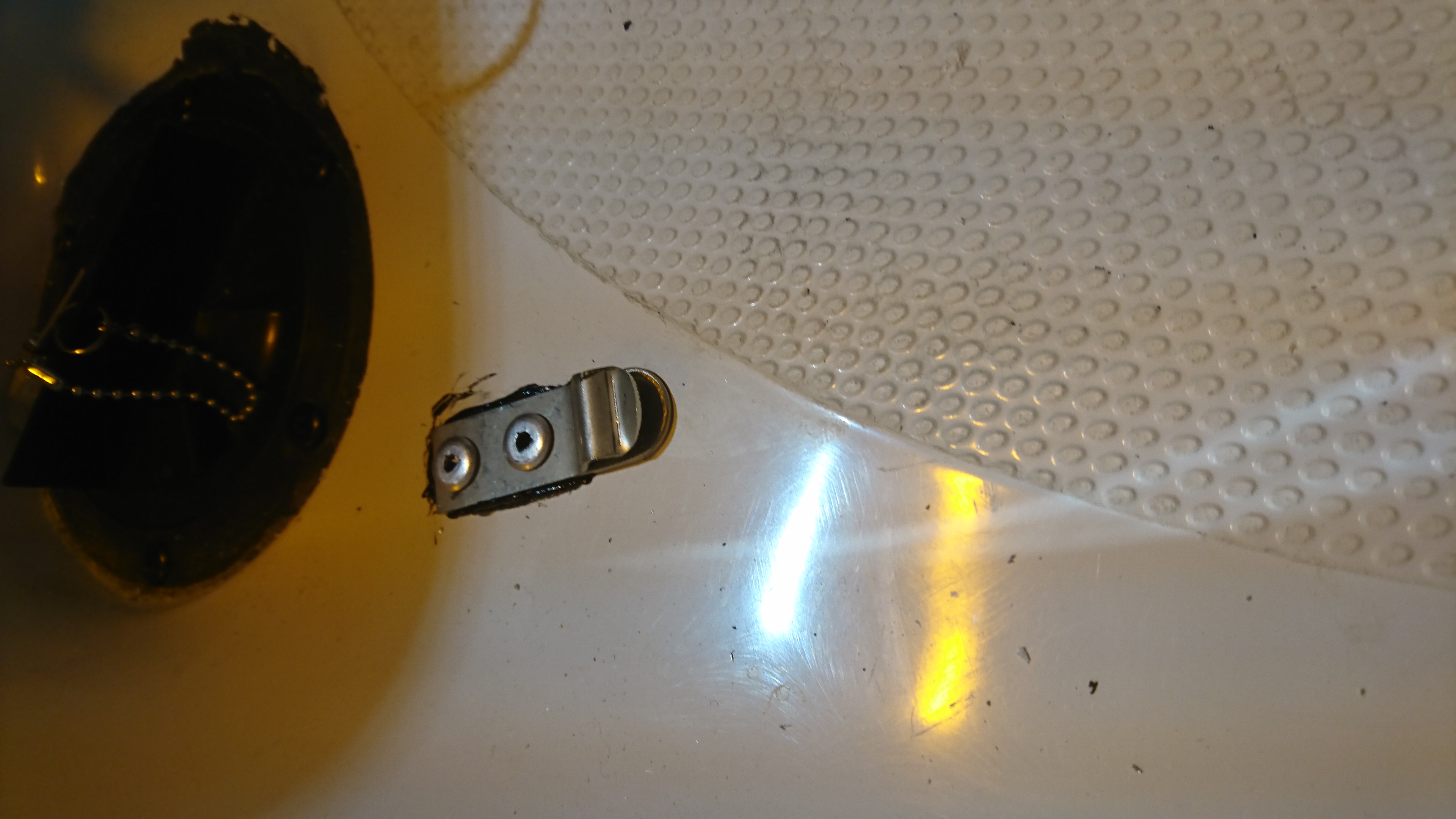
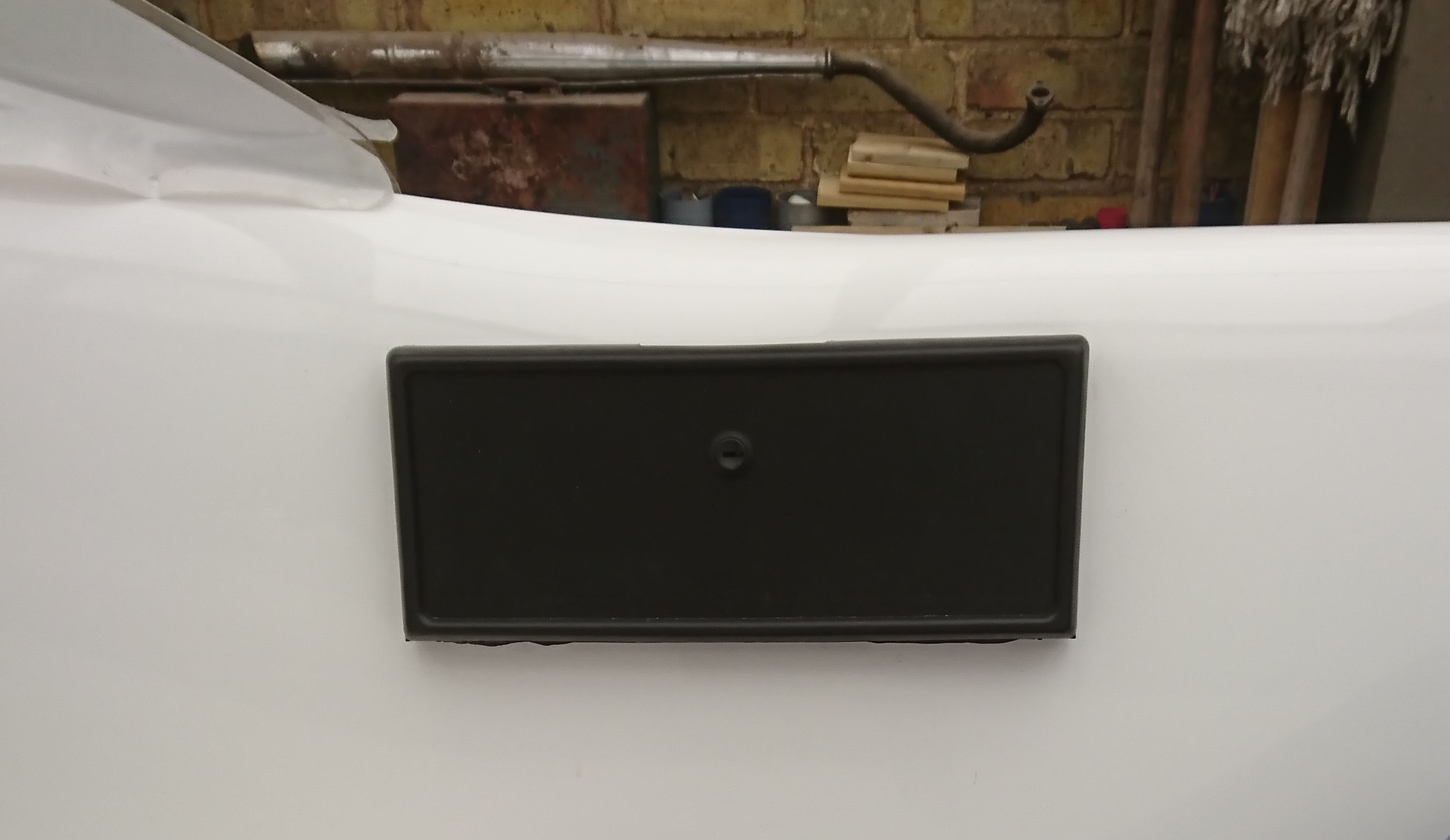
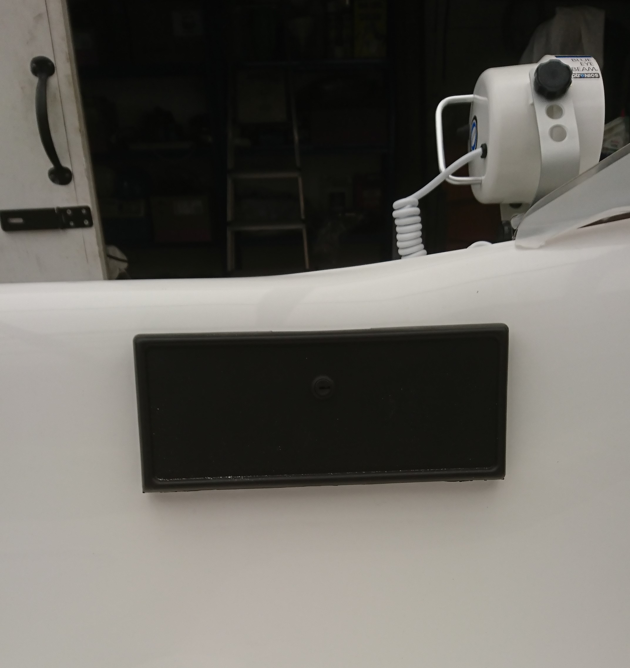
Fitting of Hull identification plate. (riveted and bonded with Devcon)
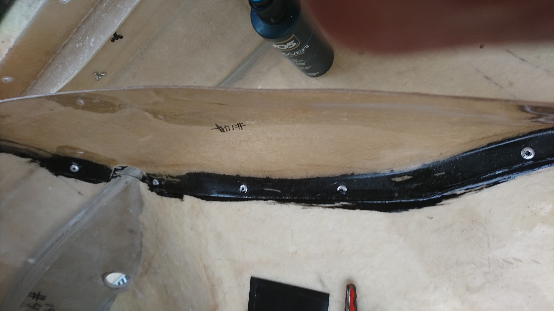
Fitting the Skirt retaining strip
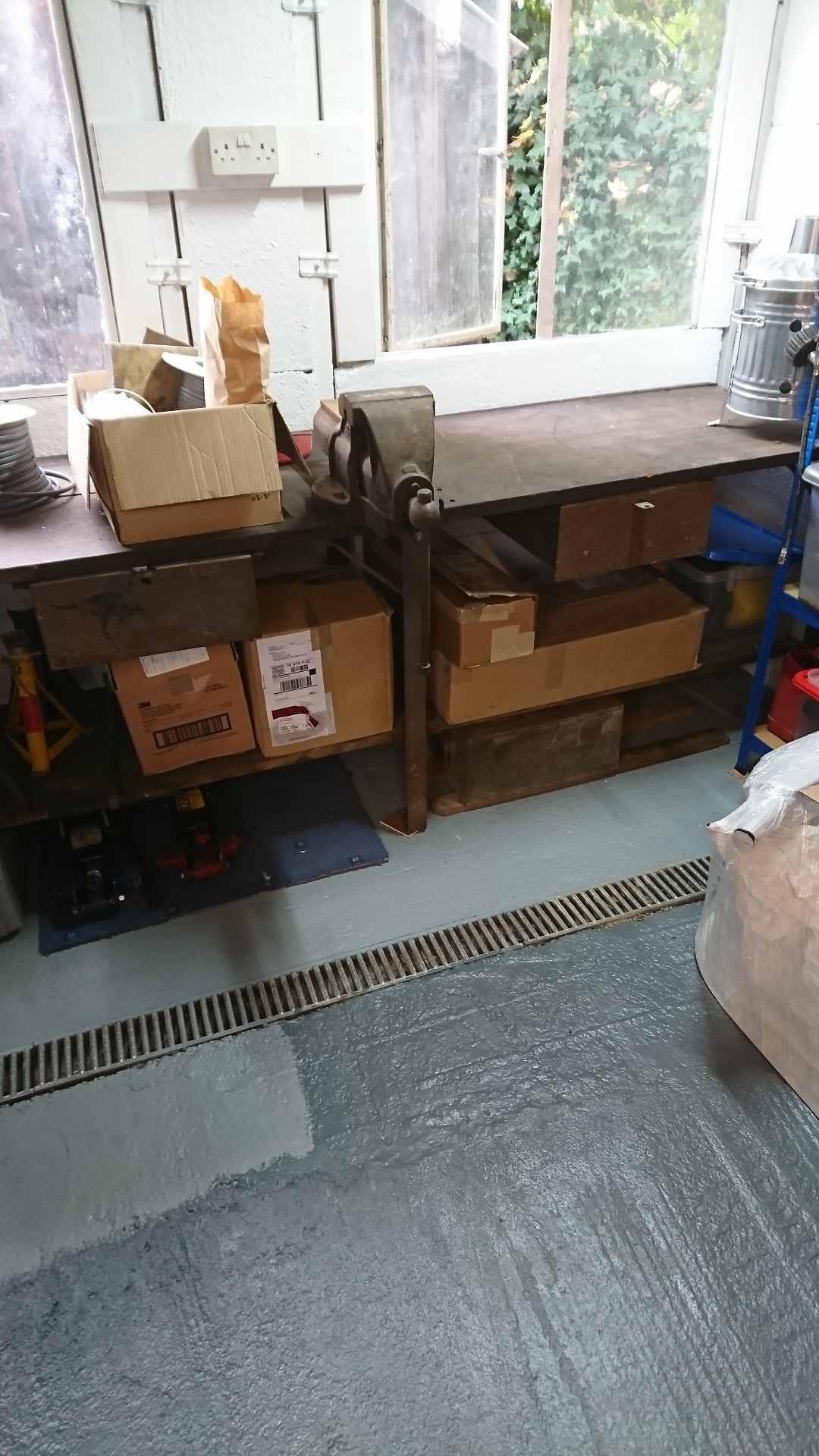
General view of working area
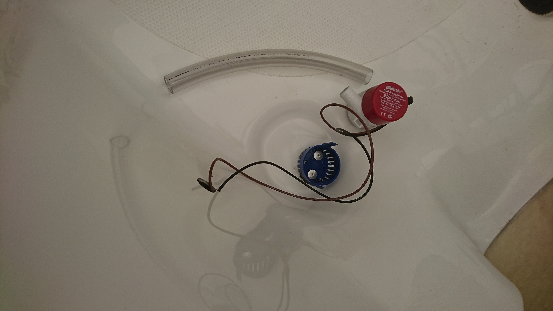
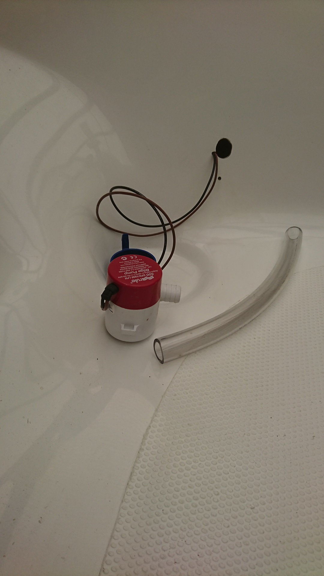
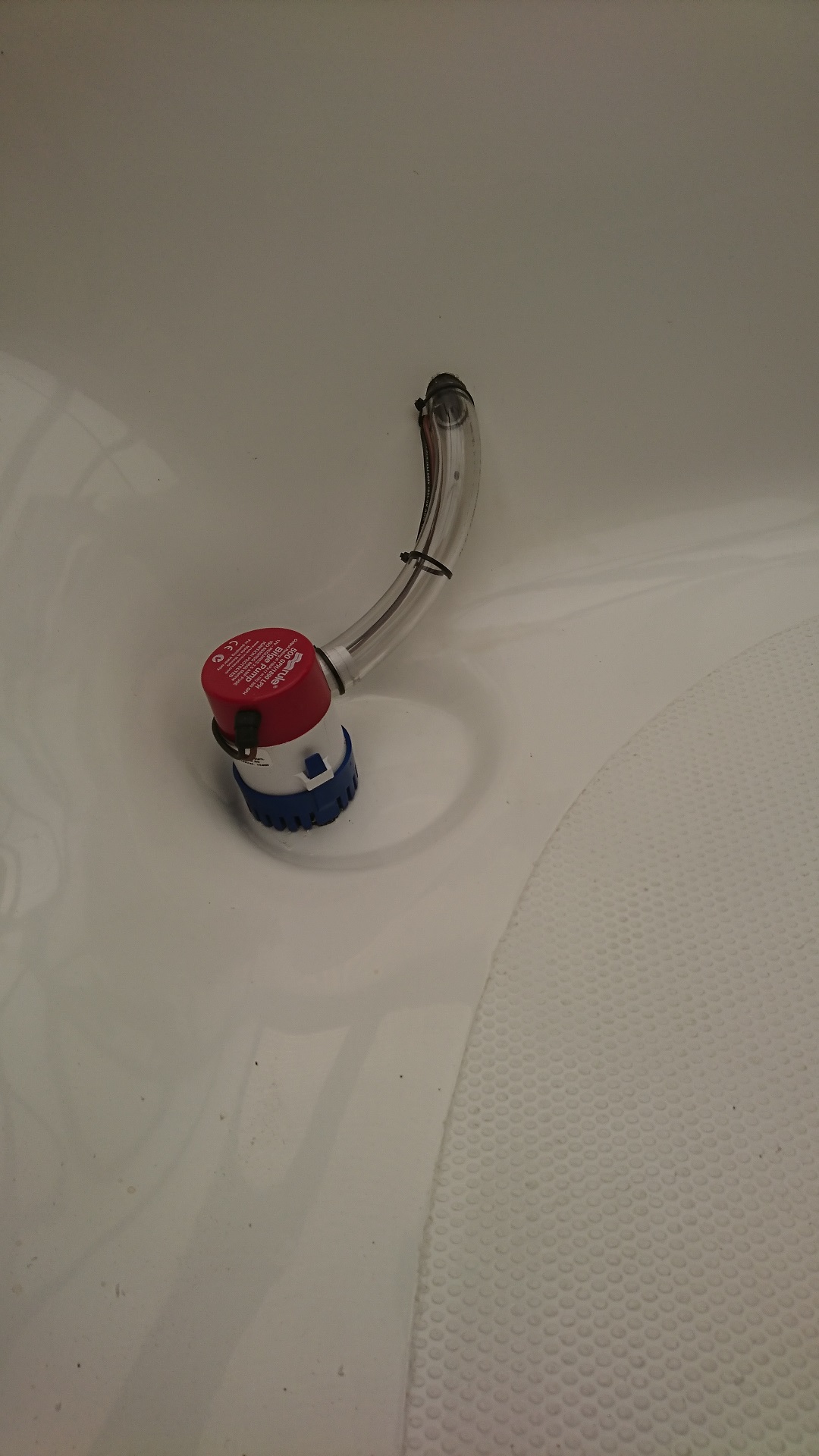
Bilge-pump with base fitted in its well
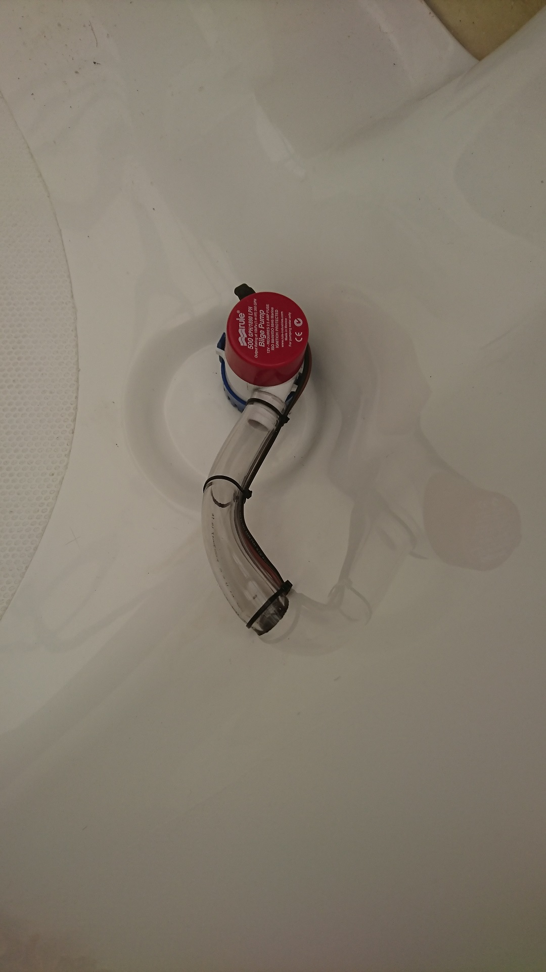
Bilge-pump with wiring and hole for outlet pipe
Bilge-pump fitted, another view
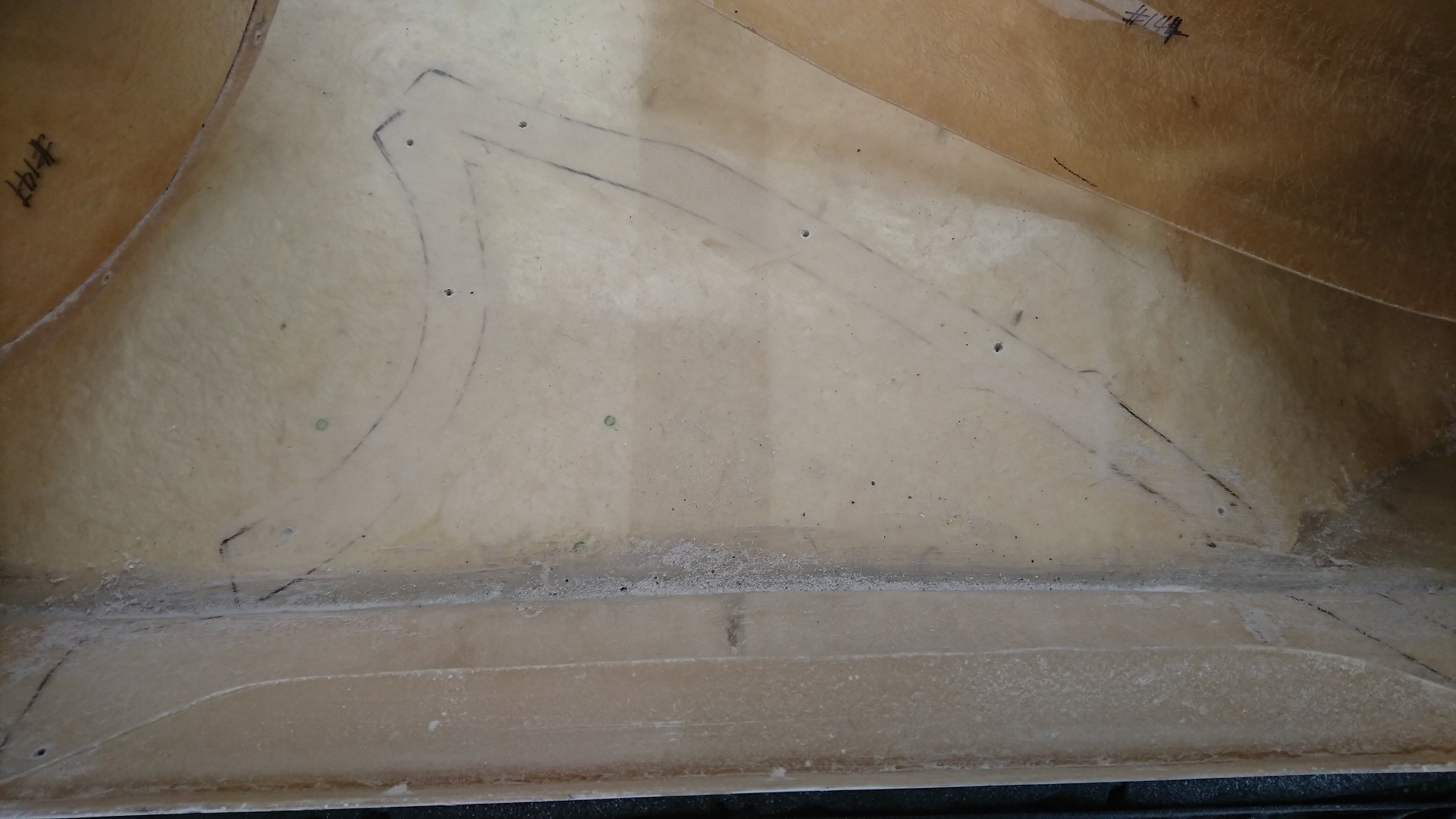
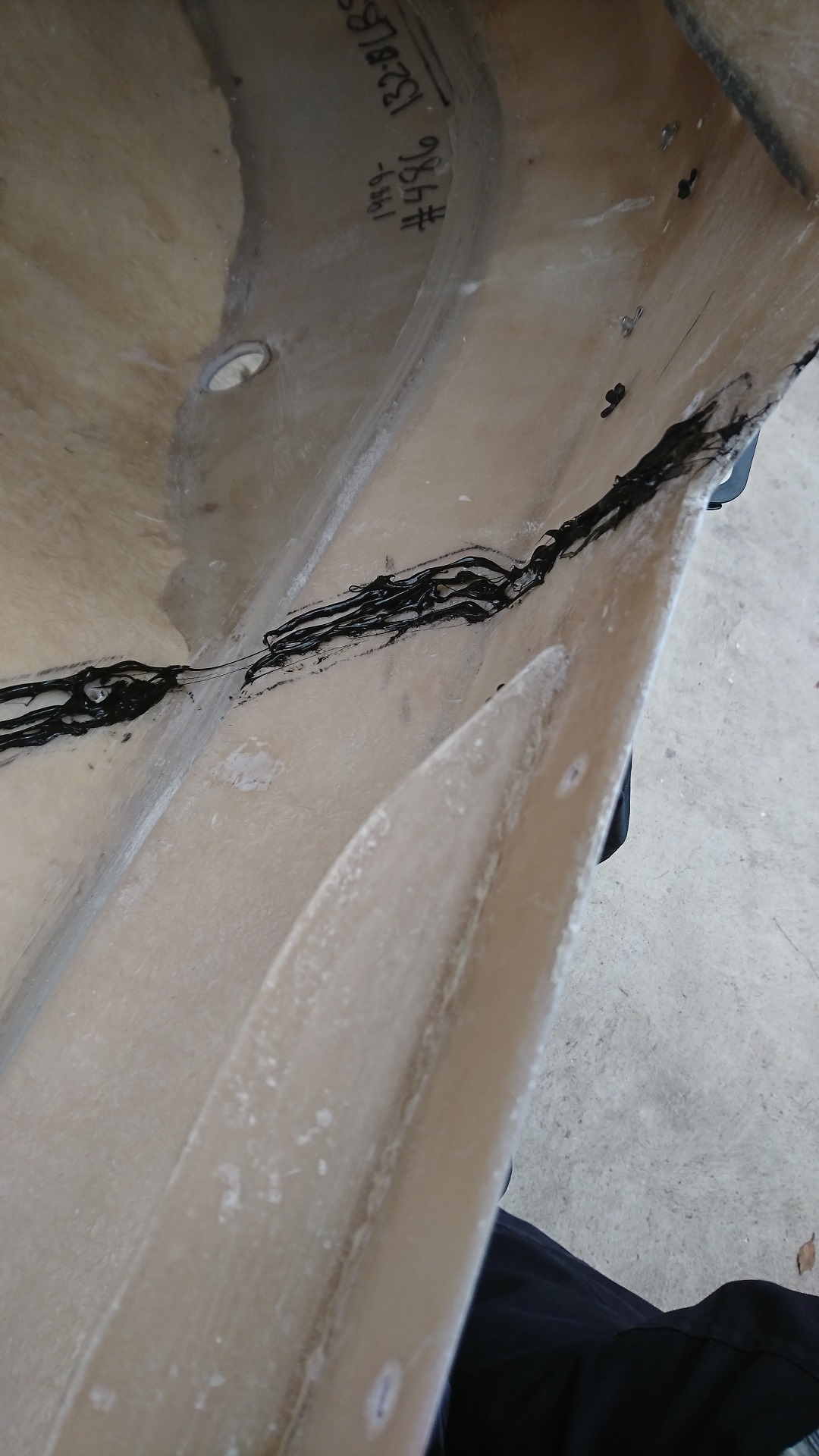
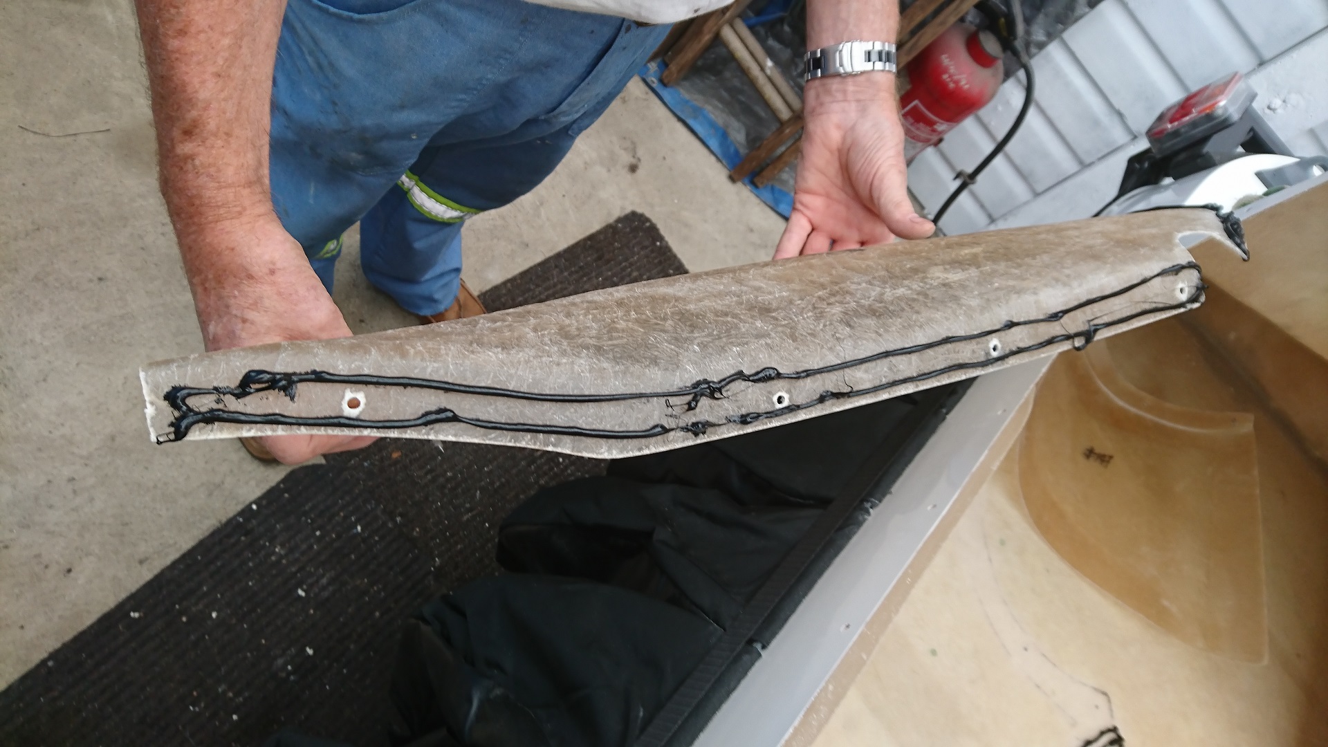
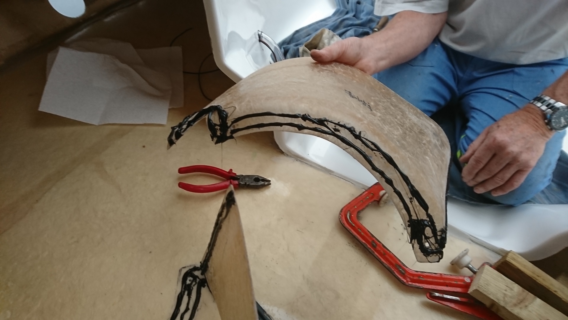
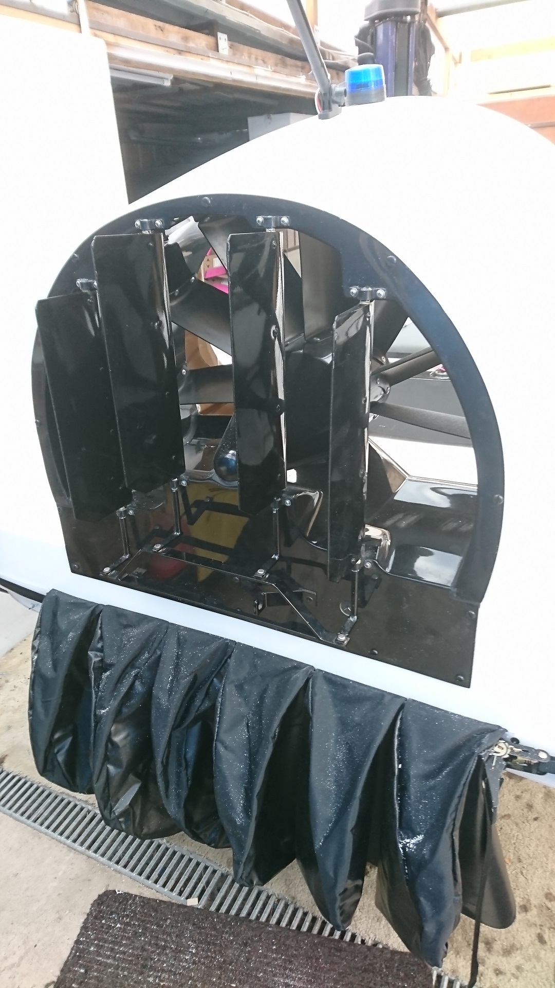
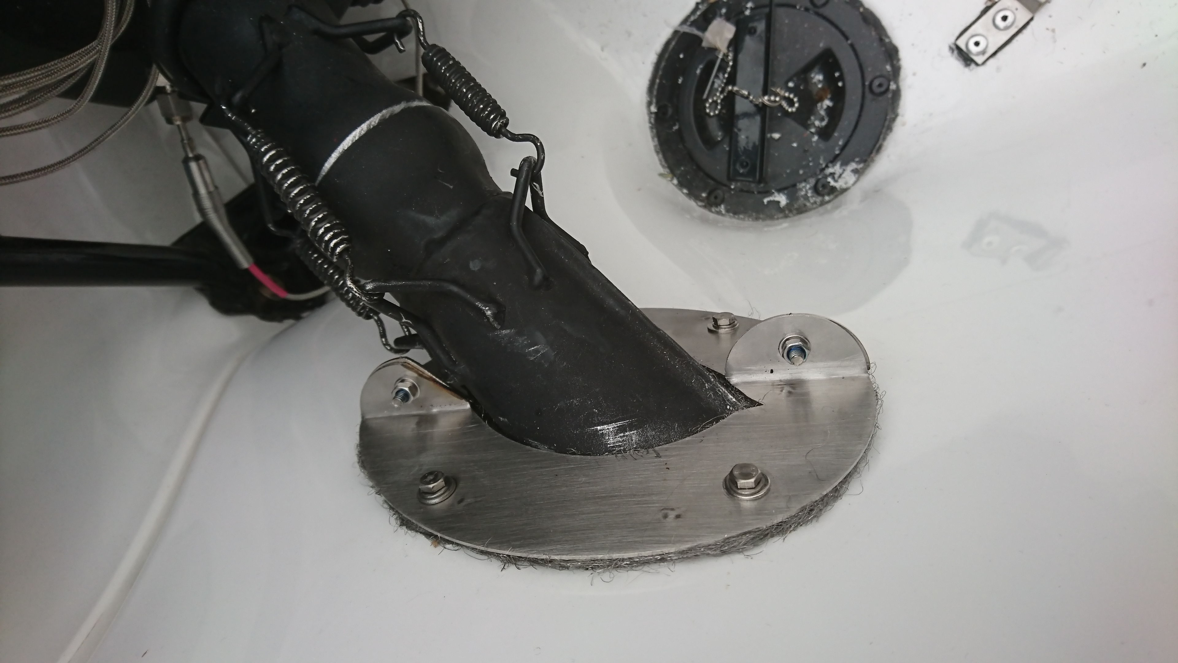
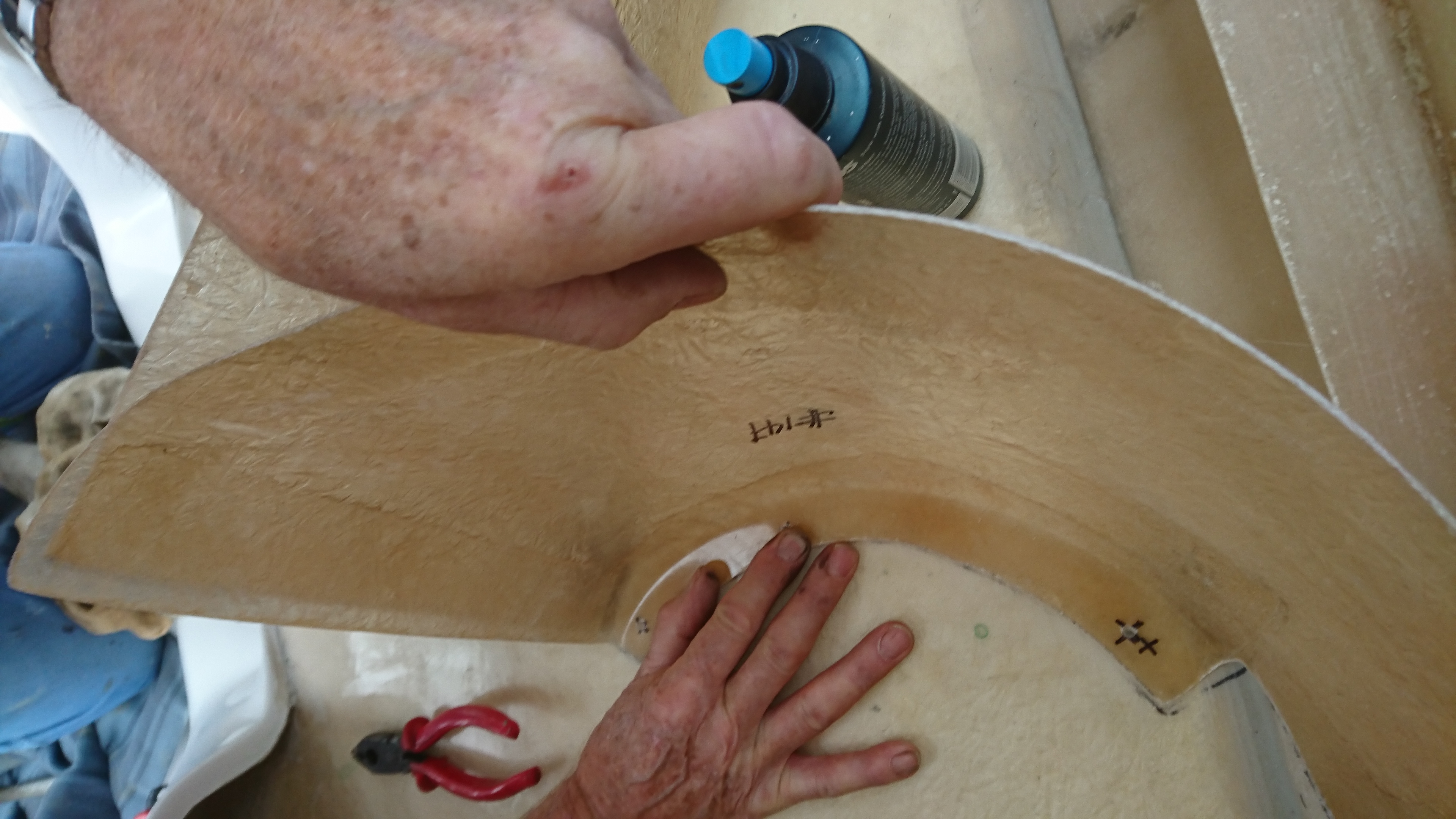
Splitter plates marked out
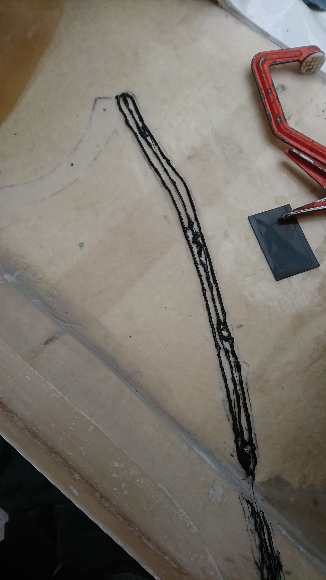
Starboard Splitter plate position with Sikaflex
Path of Starboard side splitter plate
Starboard Splitter plate prepared
Starboard Splitter plate fitted (note Sikaflex)
Port Splitter plate position with Sikaflex
Port Splitter plate +Sikaflex before fitting
Port Splitter plate fitted (note Sikaflex)
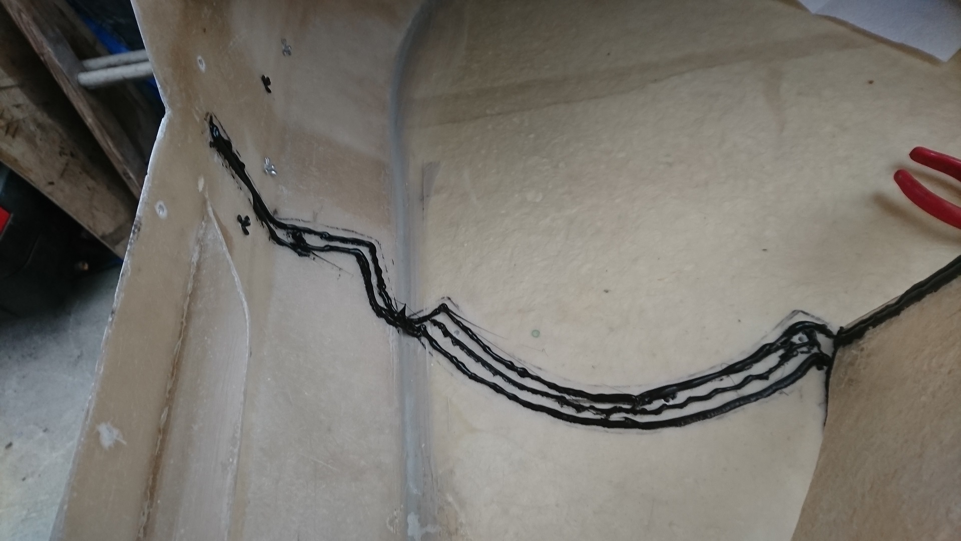
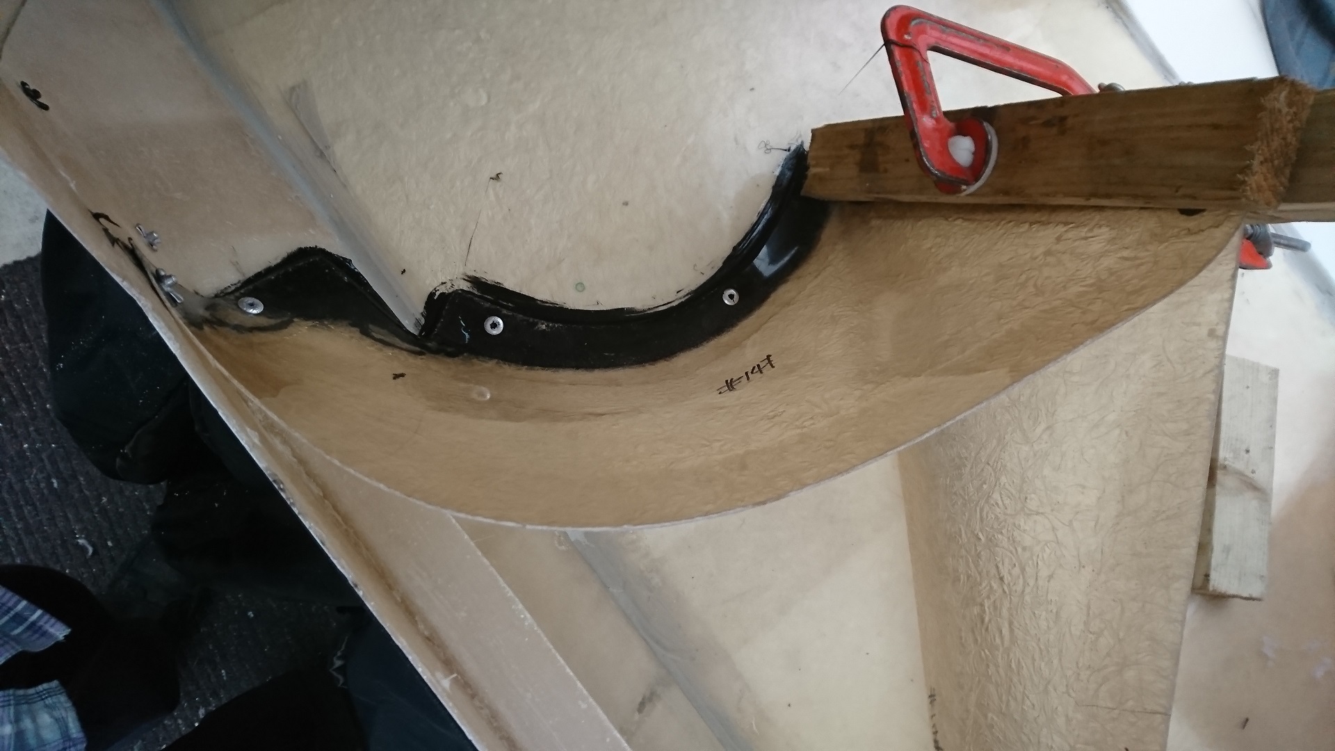
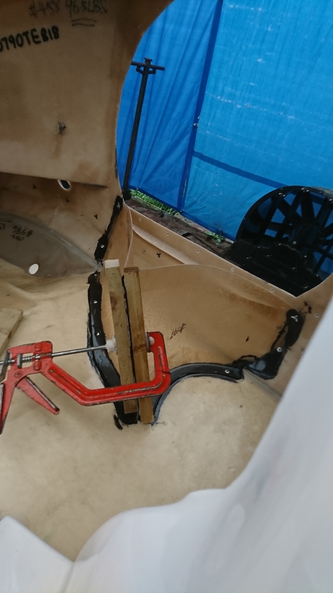
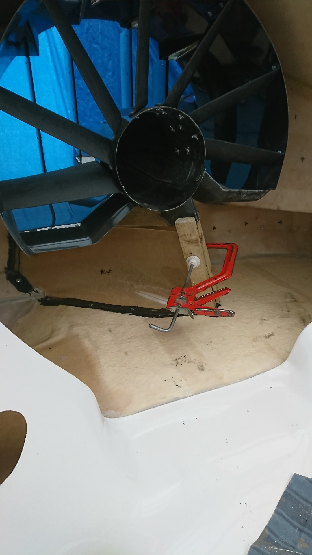
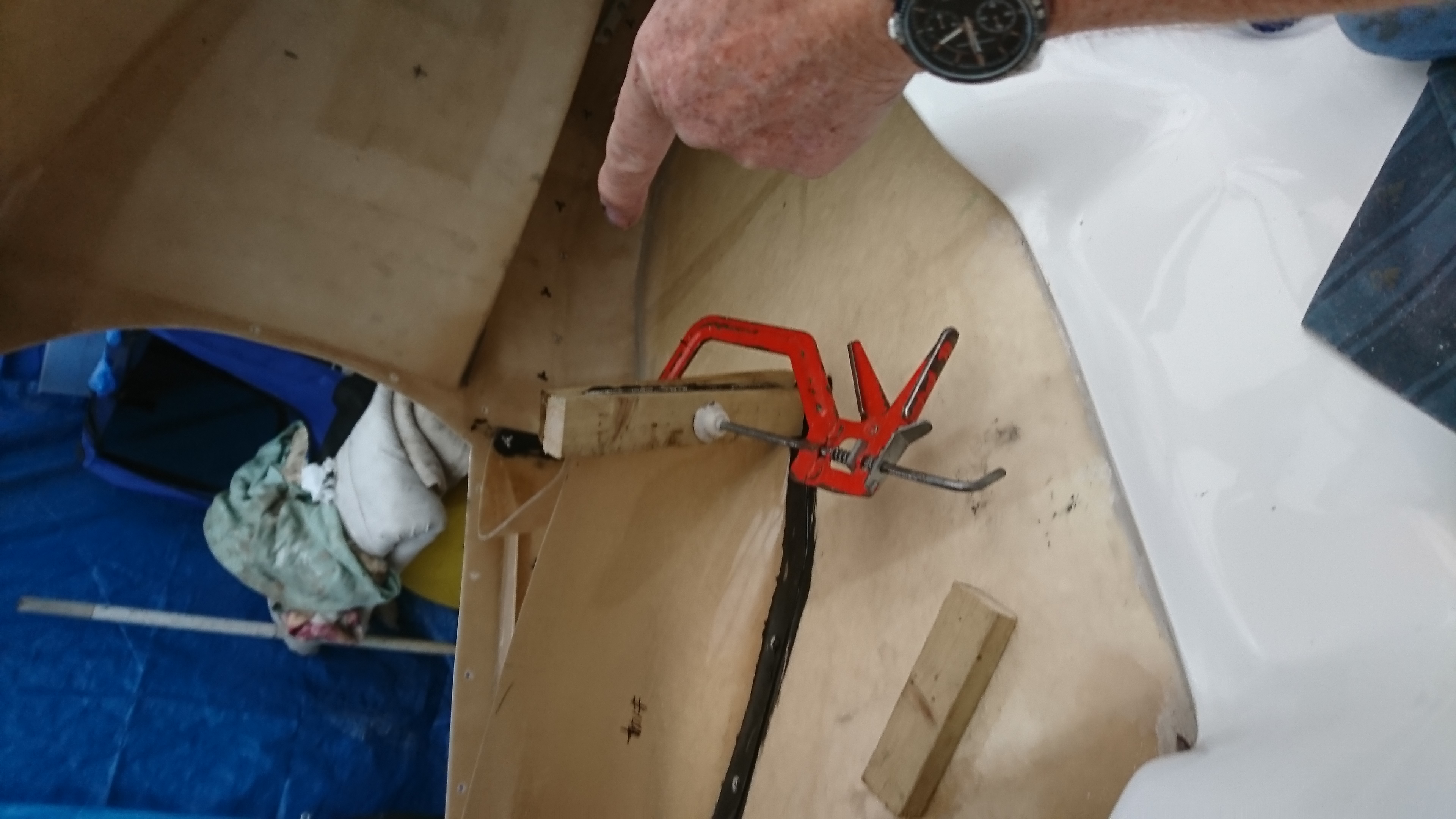
Both Splitter plates fitted and clamped
Both splitter plate being checked with duct
Splitter plates clamped and aligned with duct (left to set overnight)
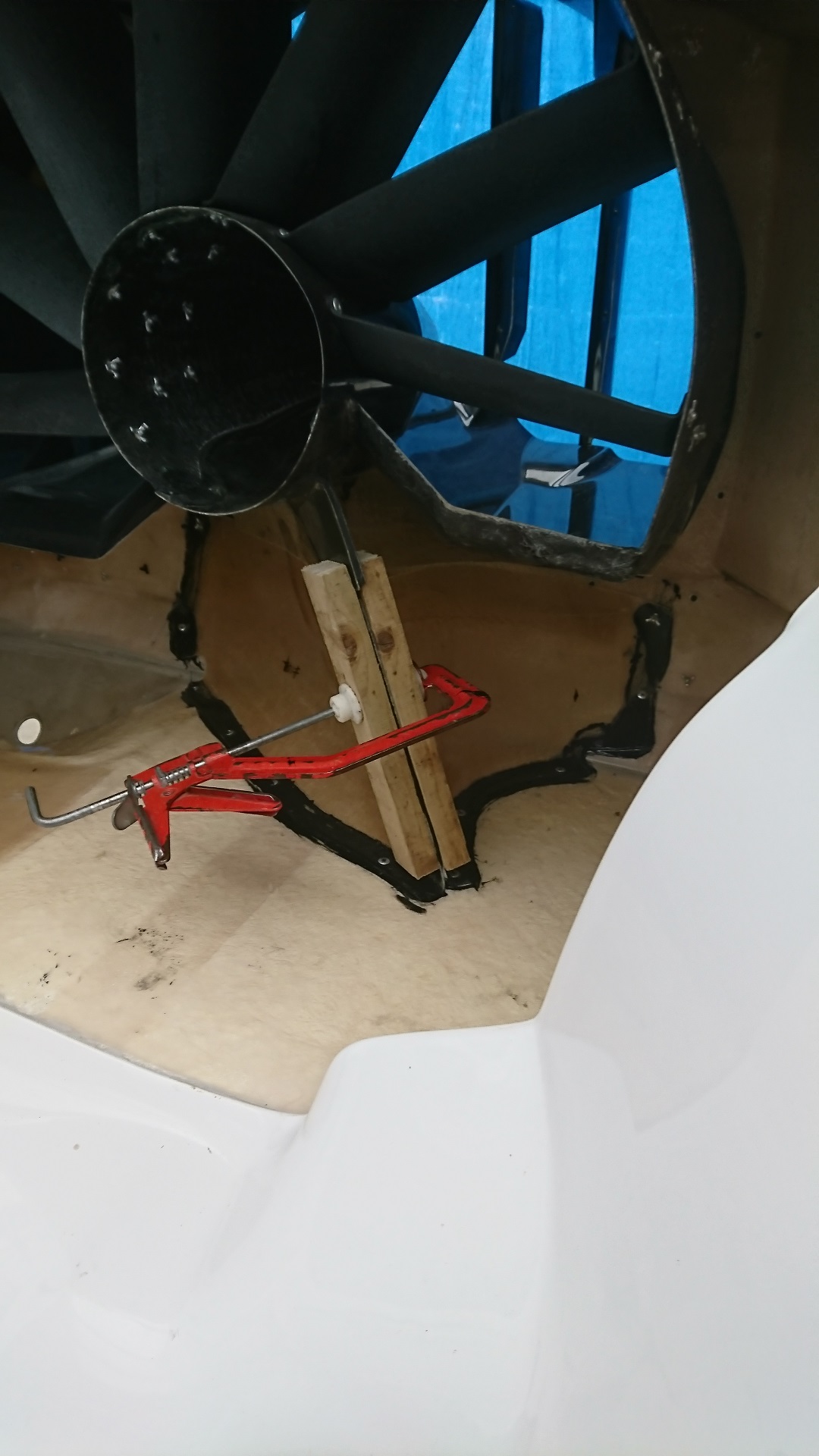
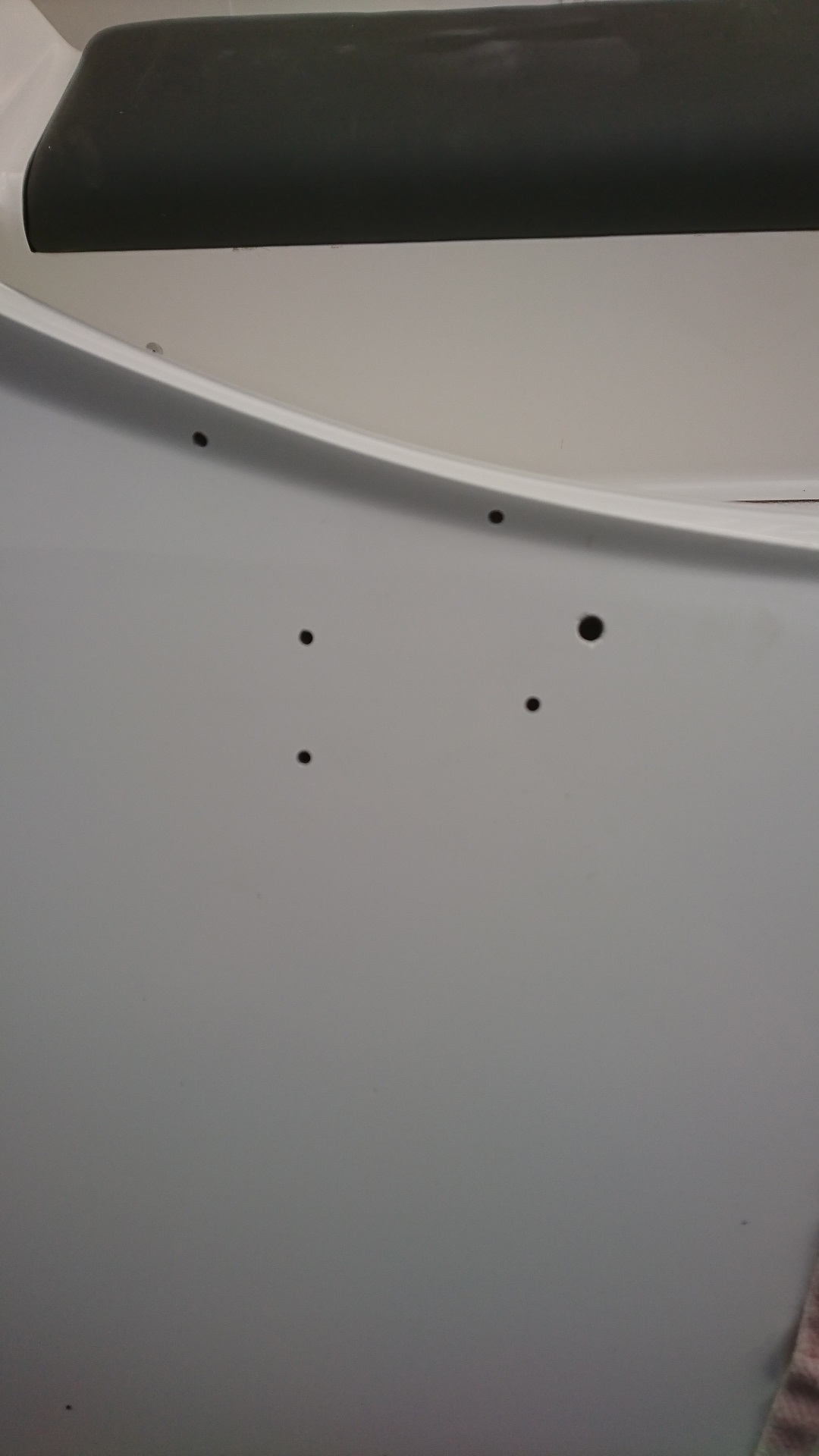
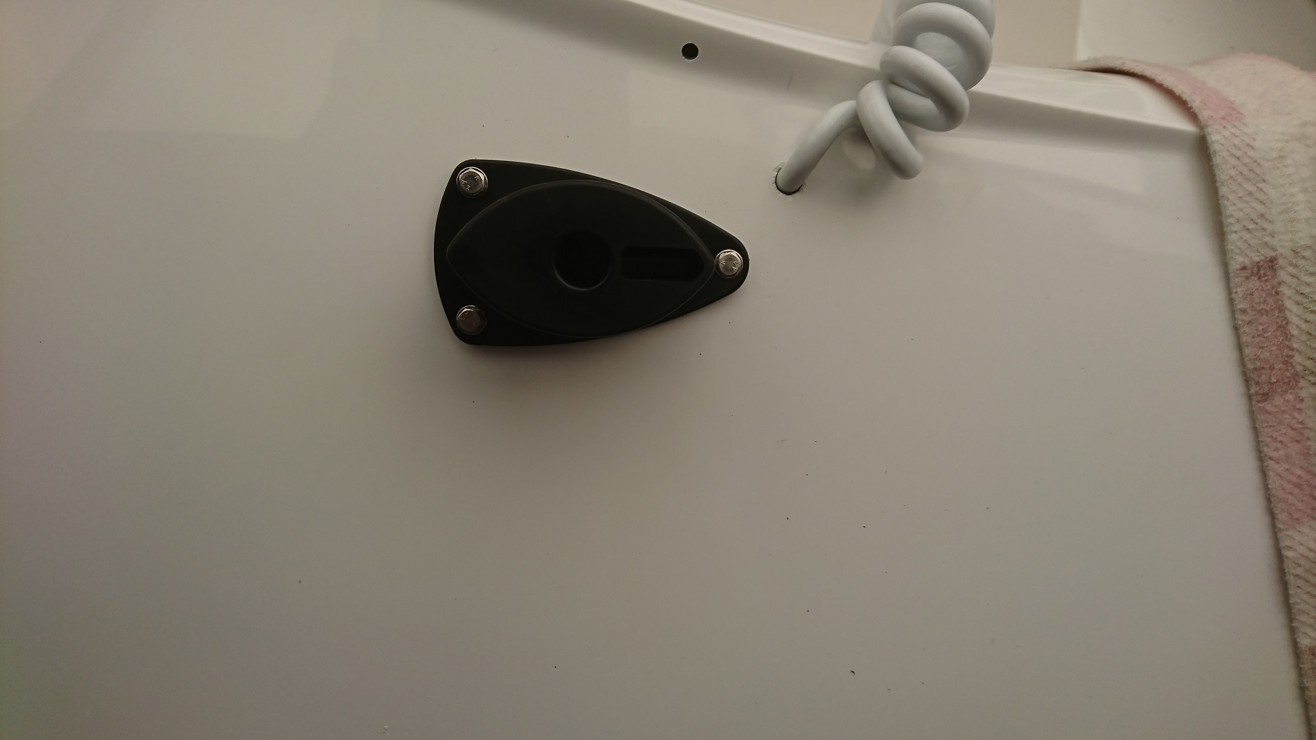
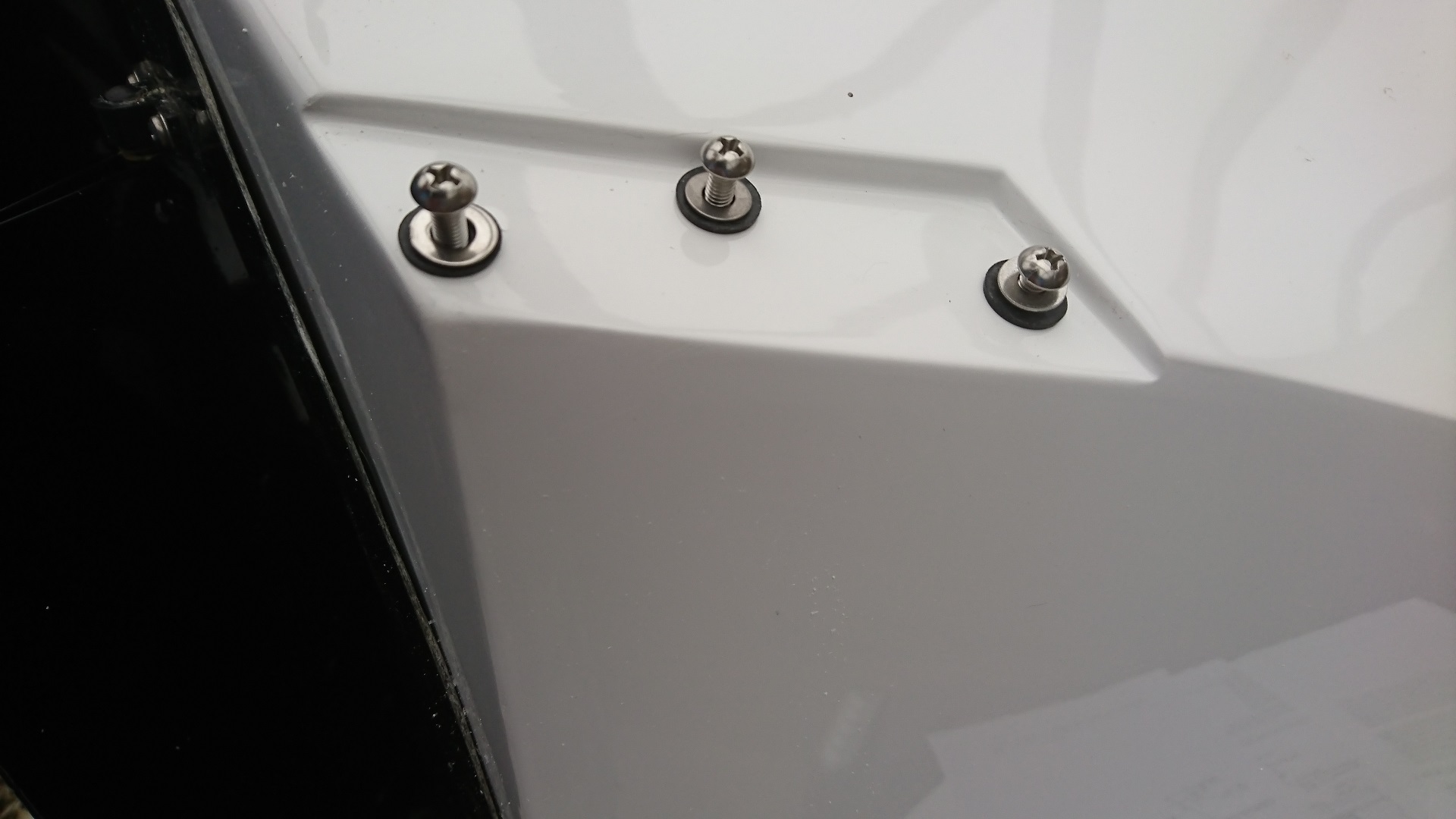
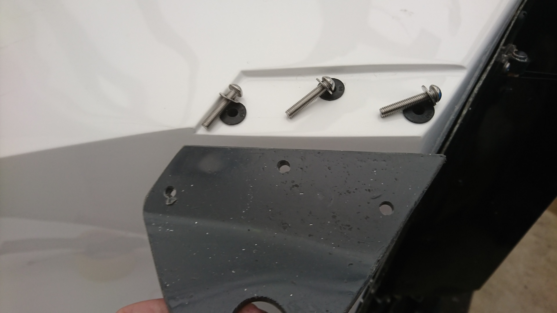
Marking out and drilling fixing for Spotlight
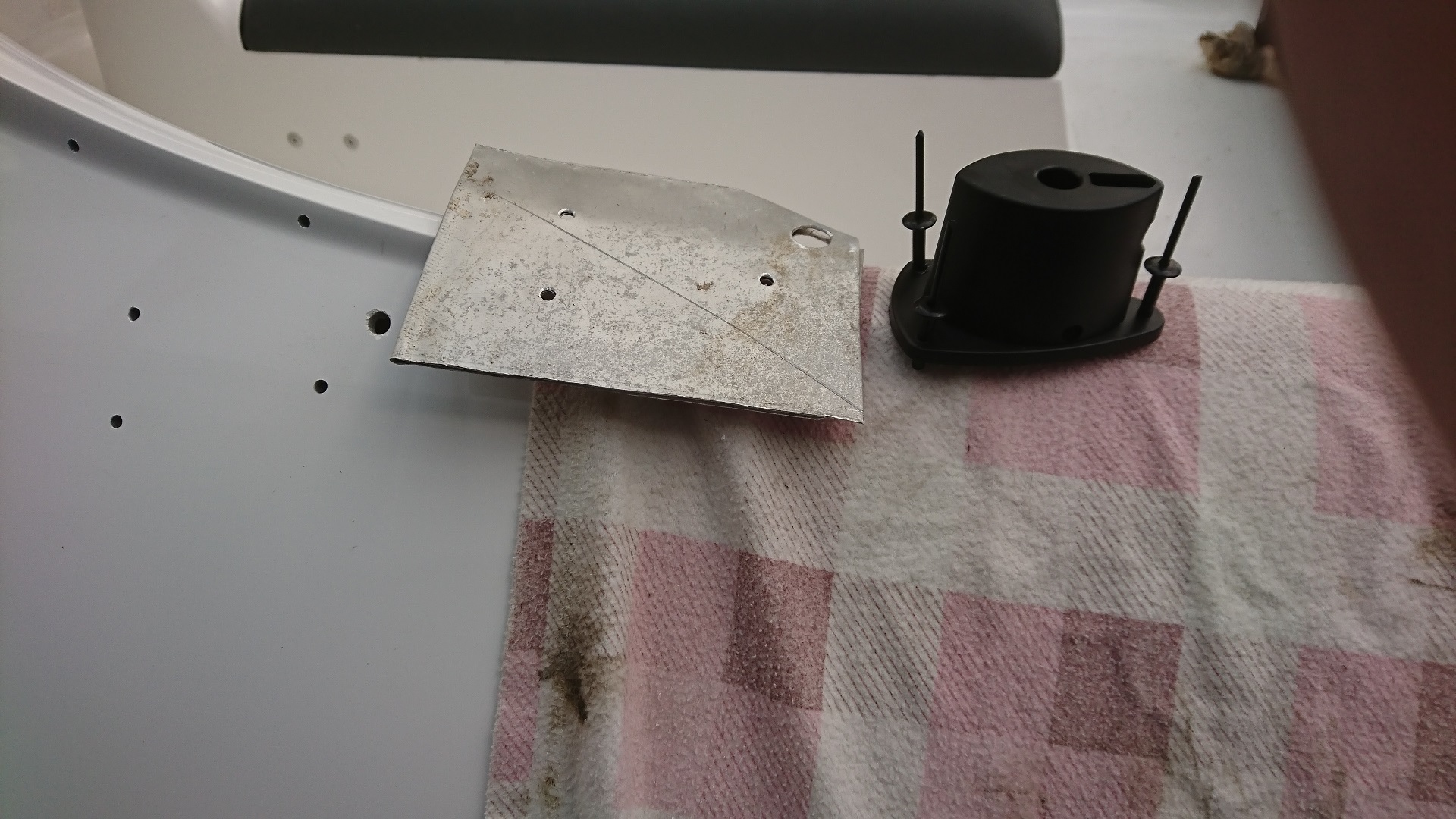
Support plate for Spotlight
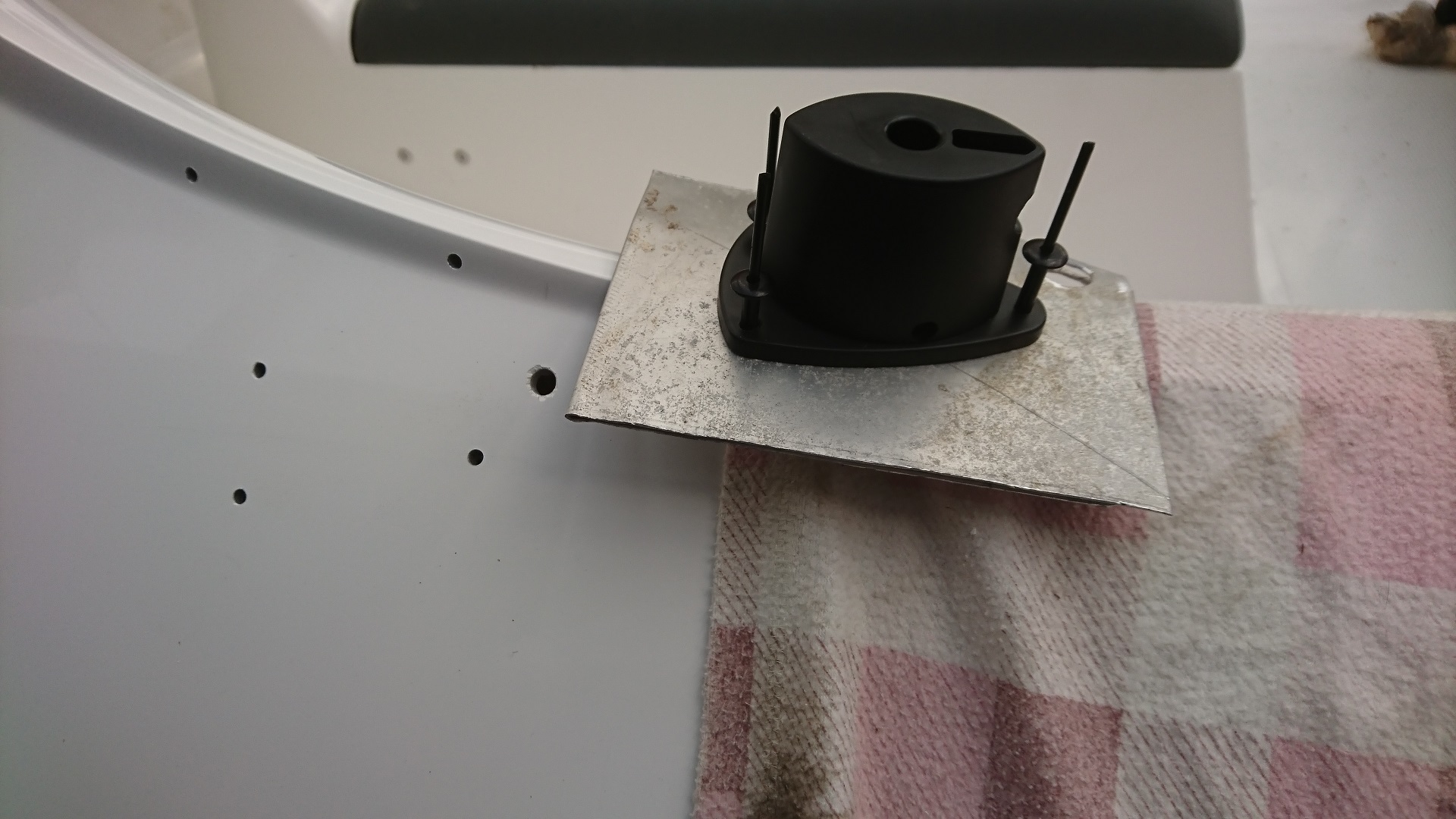
Checking fitment of support plate on mounting
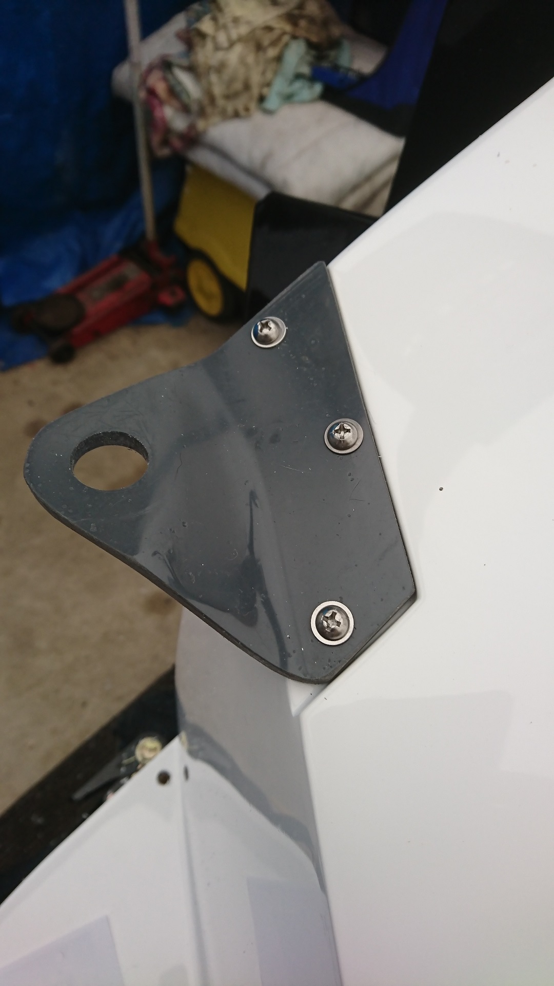
Spotlight mounting fitted
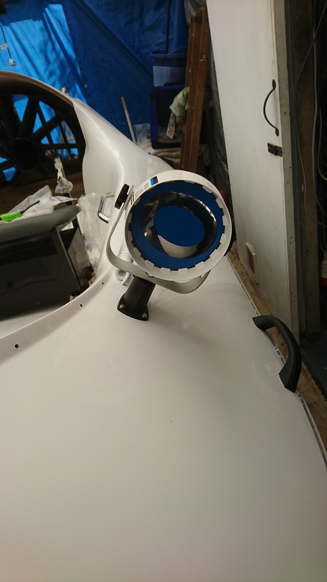
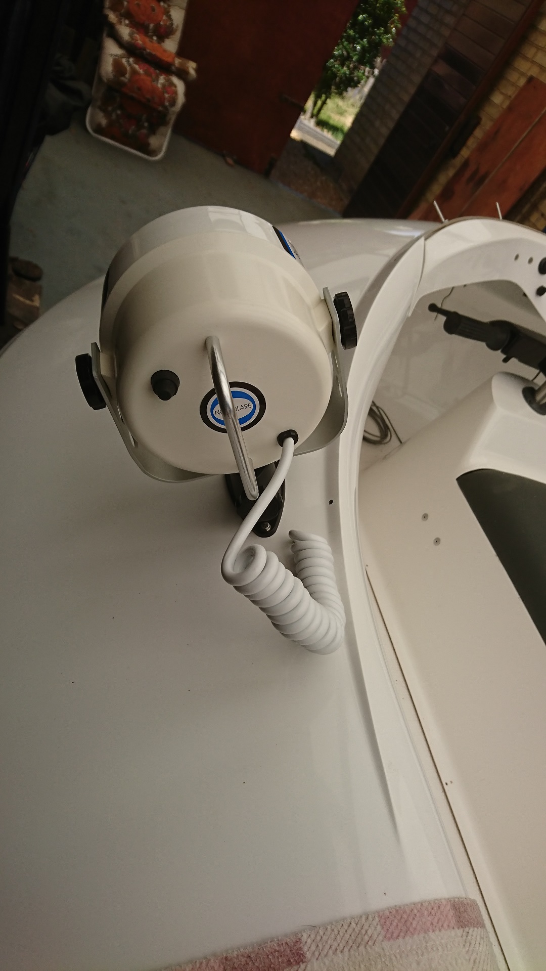
Spotlight fitted, front view
Spotlight fitted, rear view
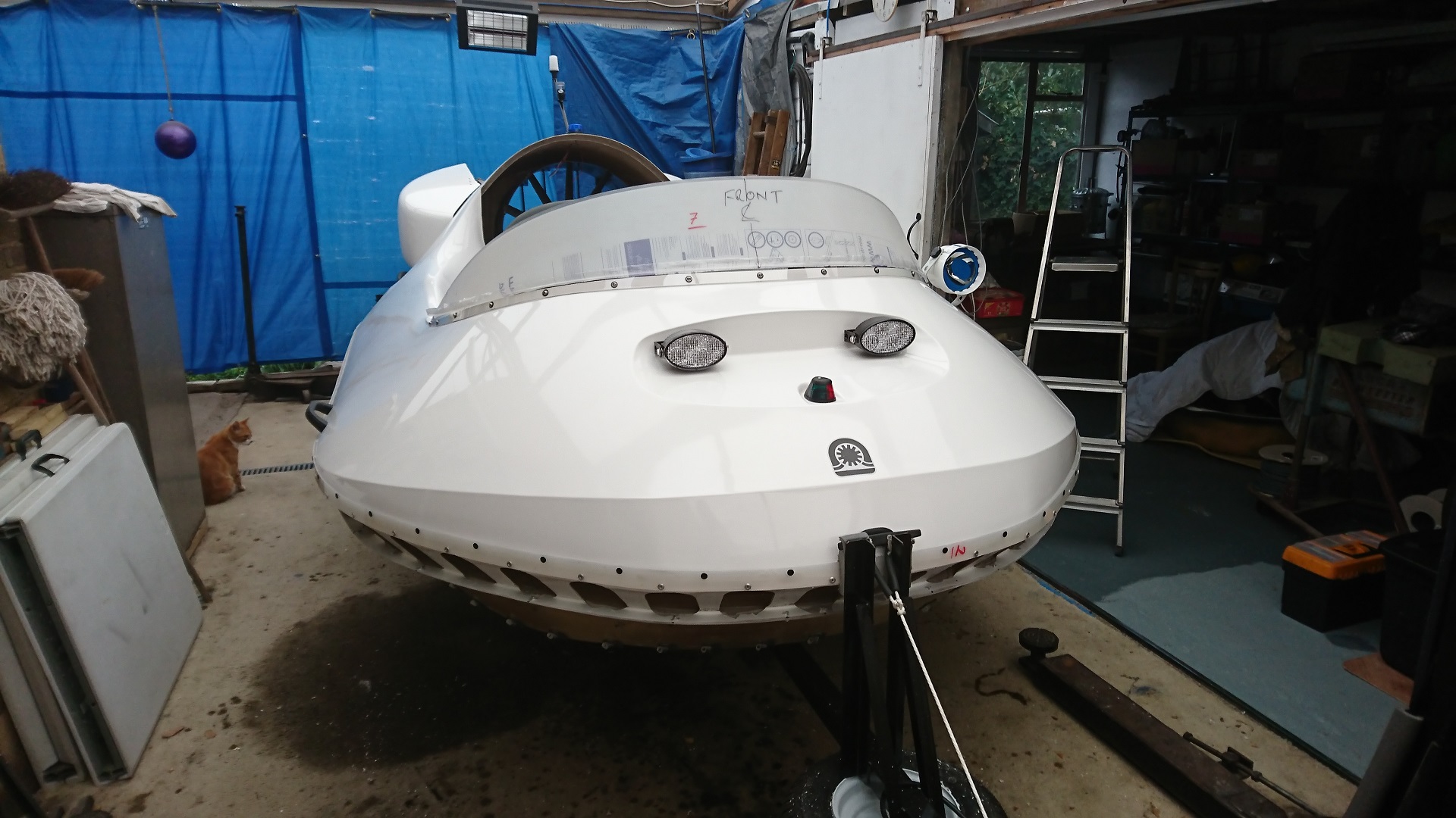
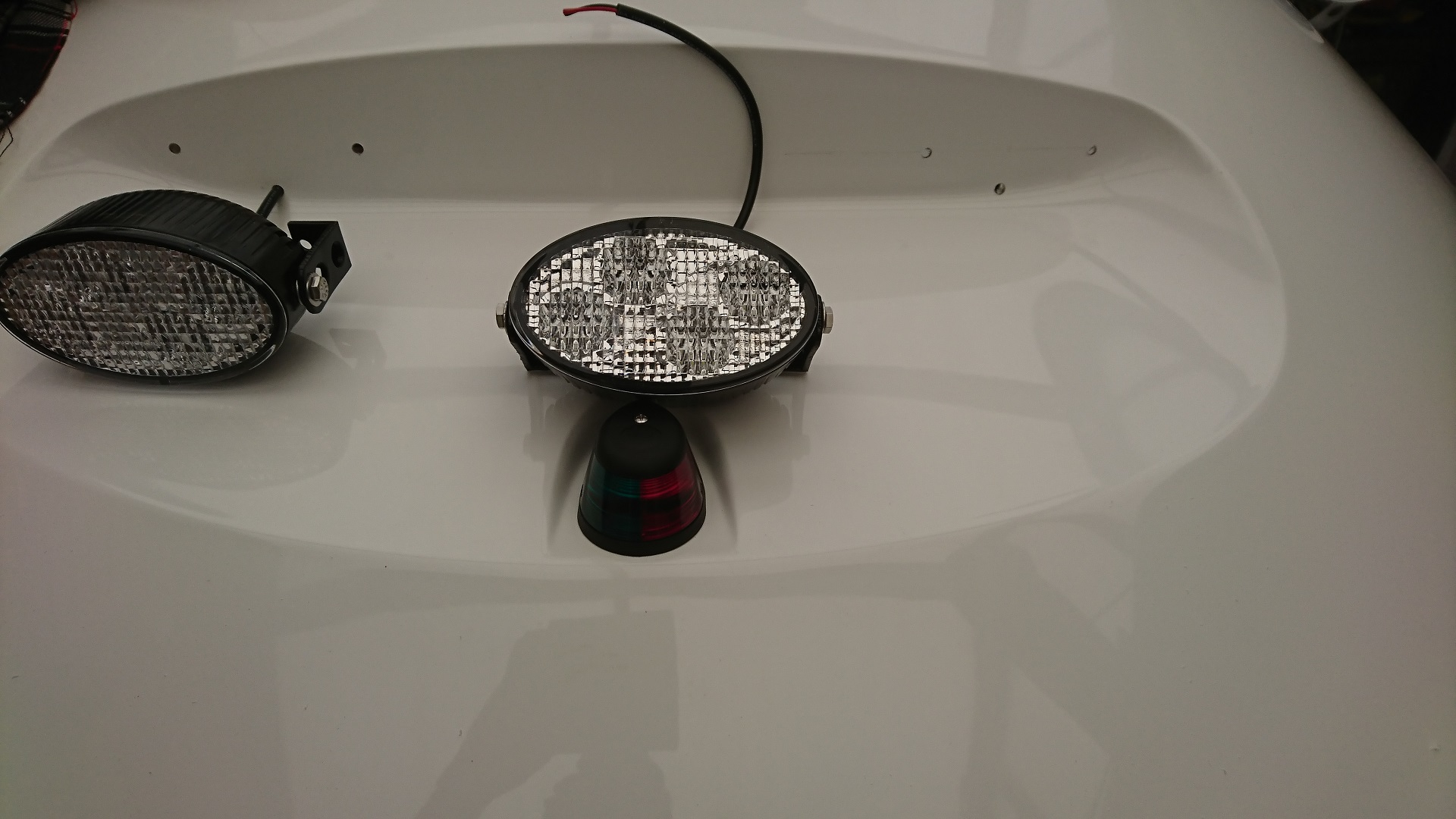
8. Headlights
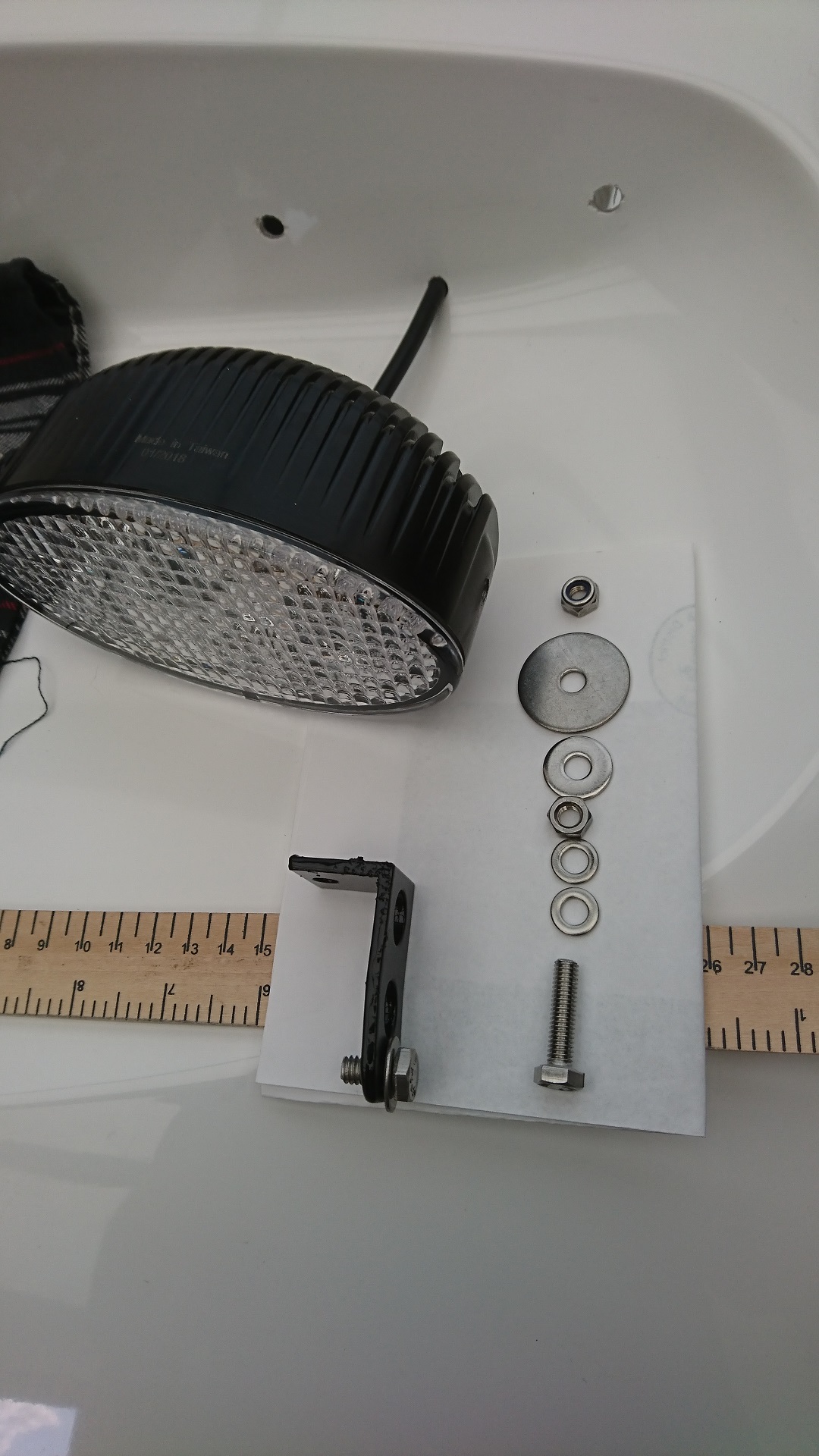
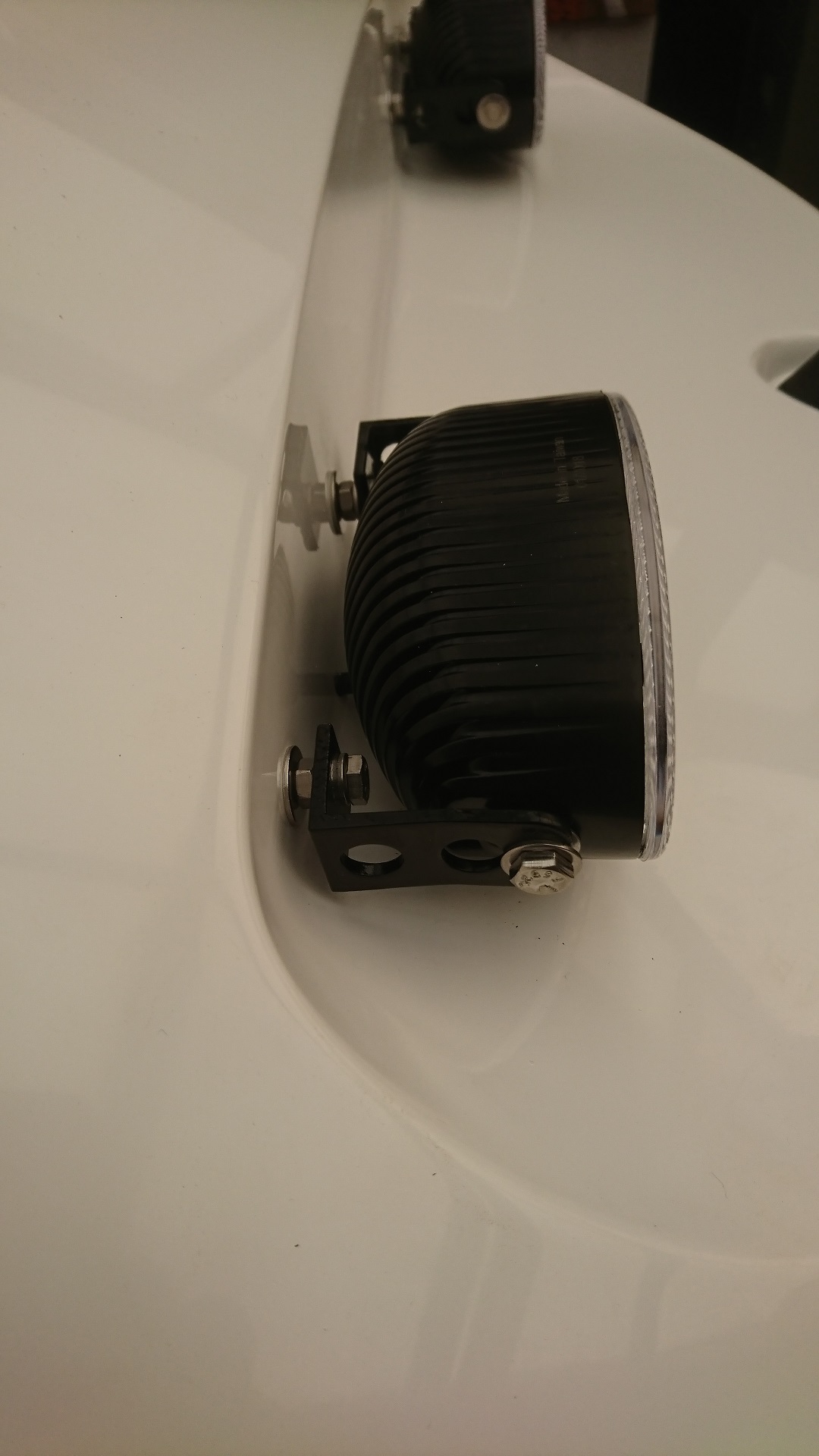
The curve of the moulding was very deceiving as to just where these lights should fit. Perhaps a paper template would be useful, just an idea. I could drill more holes and raise them, but the lights do not vibrate and seem firm enough. I do not want the front looking like a colander!
Drilling holes for Headlight brackets and wire
Another view of Headlight positions
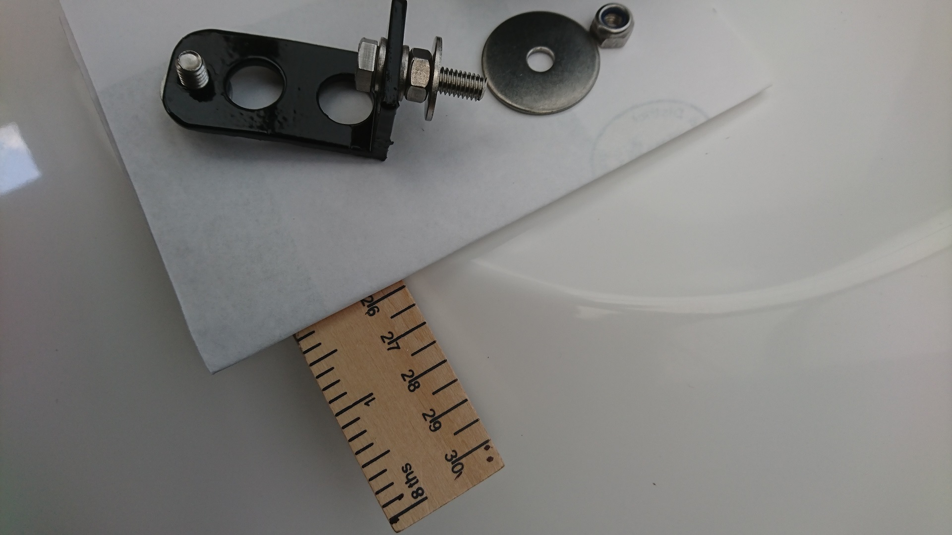
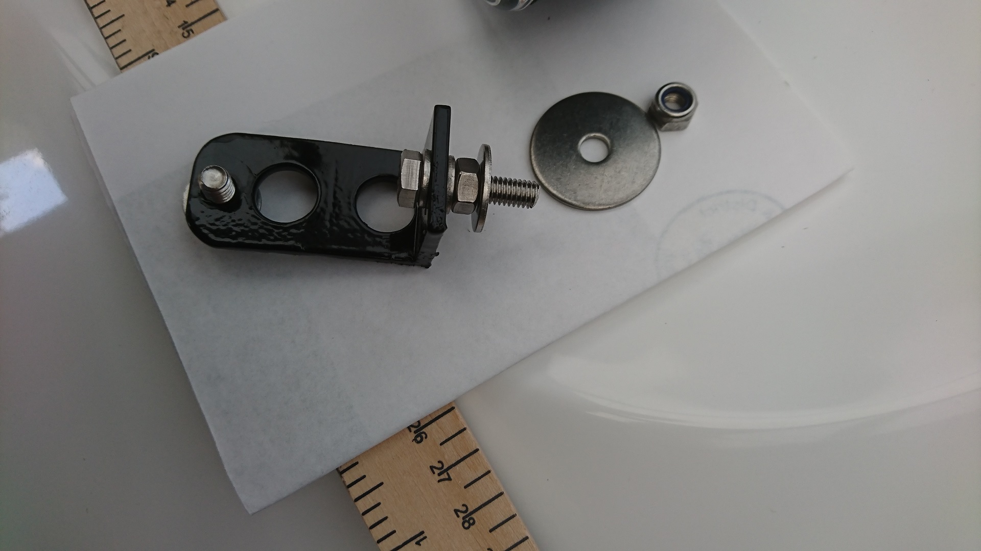
Brackets neded to be spaced and this was the set-up
Washer and bolt set-up all stainless steel
another view of set-up,large washer and nut for inside cockpit
Maybe should have fitted Headlights a shade higher,then may not have needed nuts and washers
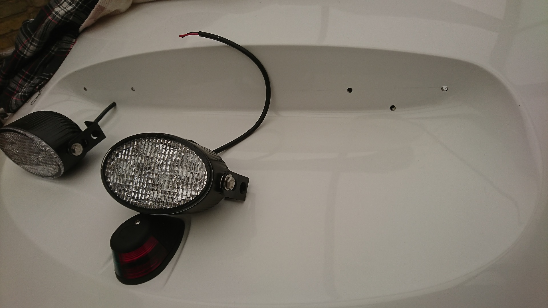
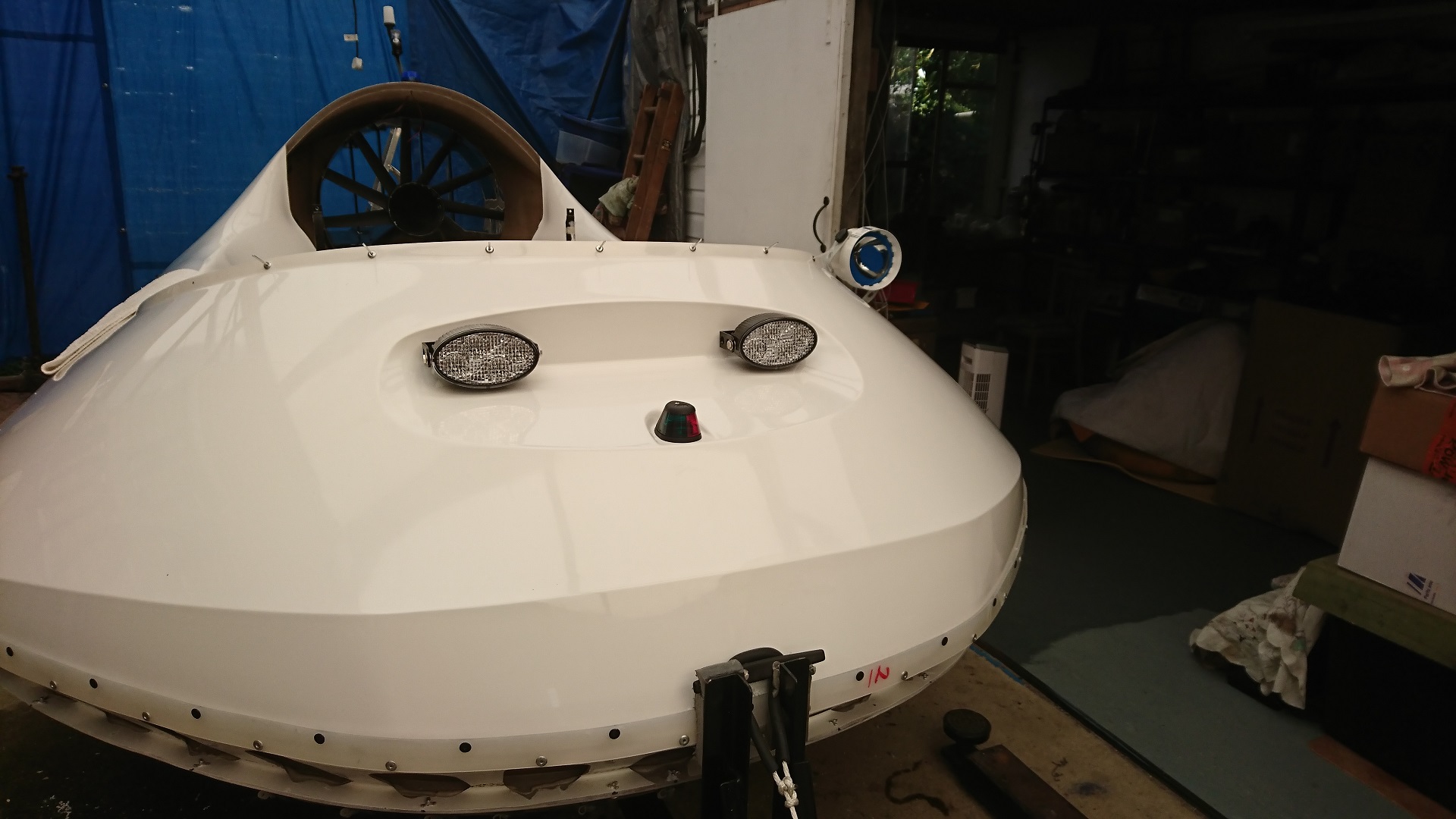
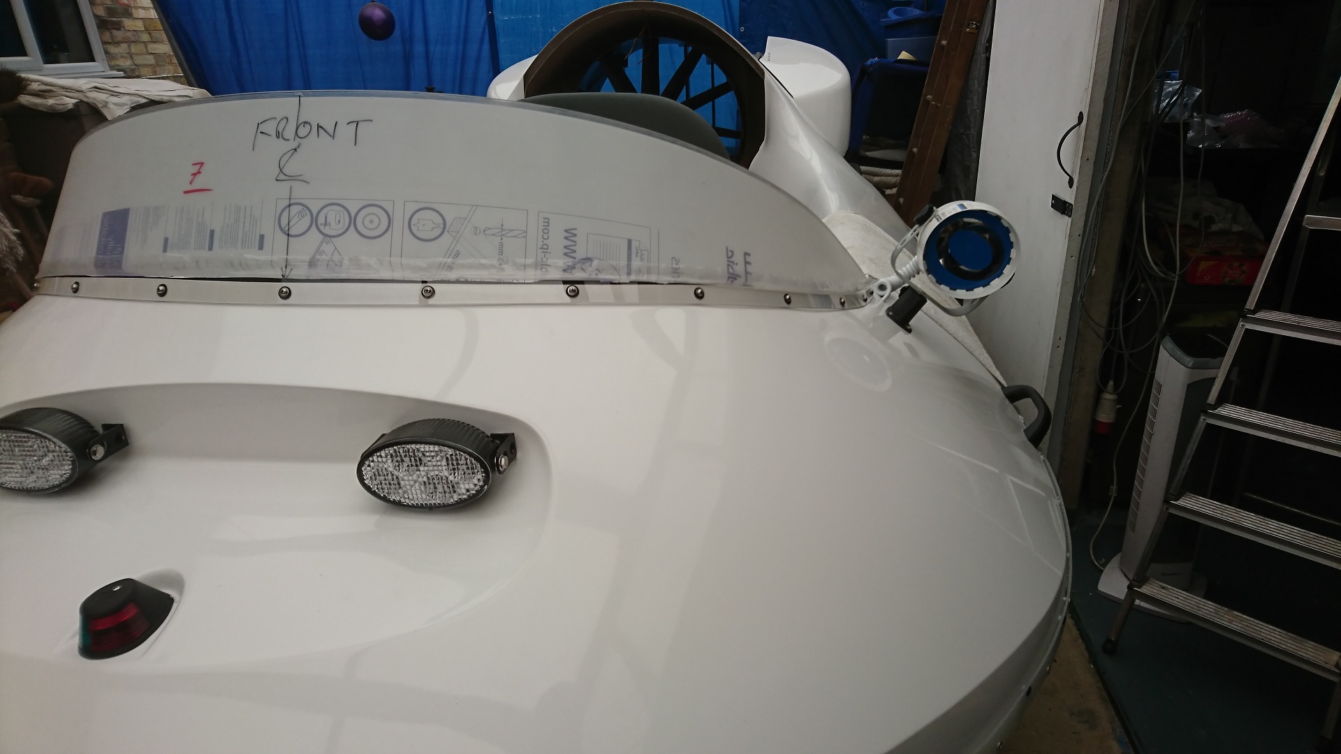
Headlights,Navigation light and Spotlight now ready to fit the Screen
Screen and navigation lights,headlights and spotlight
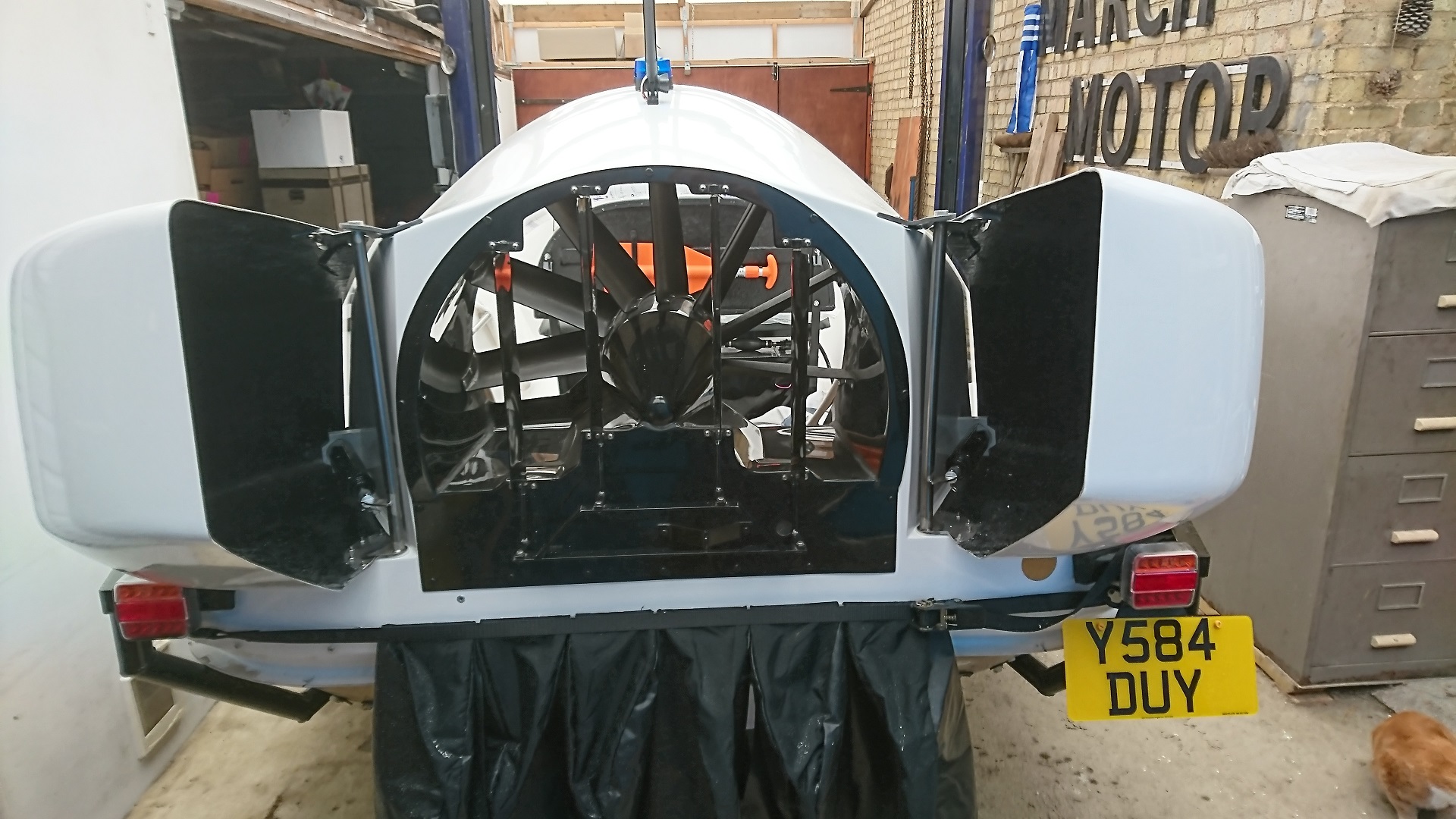
9. Reverse Thrust Ducts (Buckets)
Captions tell most of the story. The bottom bearing holes and operating solenoids and computer control box are fitted as per the instructions. Drill small 3/16th hole at lower bearing position first and increase to 1/2" then to 3/4", checking alignment with upper bearing bracket as you go. This enables you to file the last bit if you need to re-align the pivot.
Reverse Thrust Bucket upper bracket location
Reverse Thrust Bucket screws,washers and well-nuts
Reverse Thrust Bucket bracket,well-nuts and screws
Reverse Thrust Bucket bracket completed
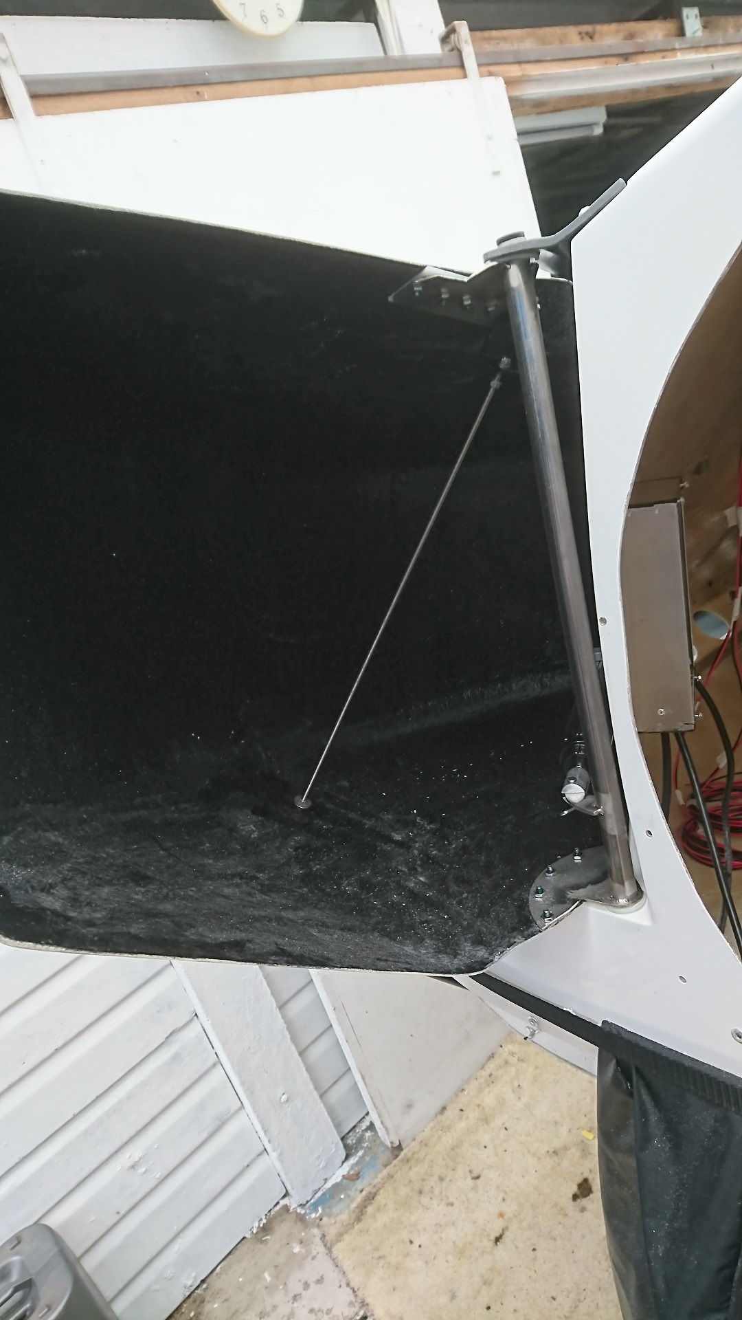
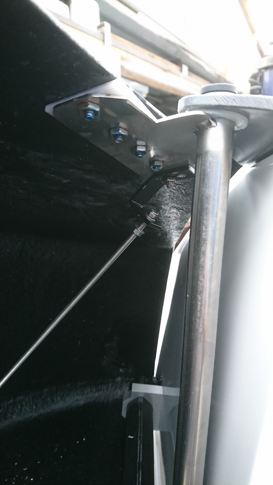
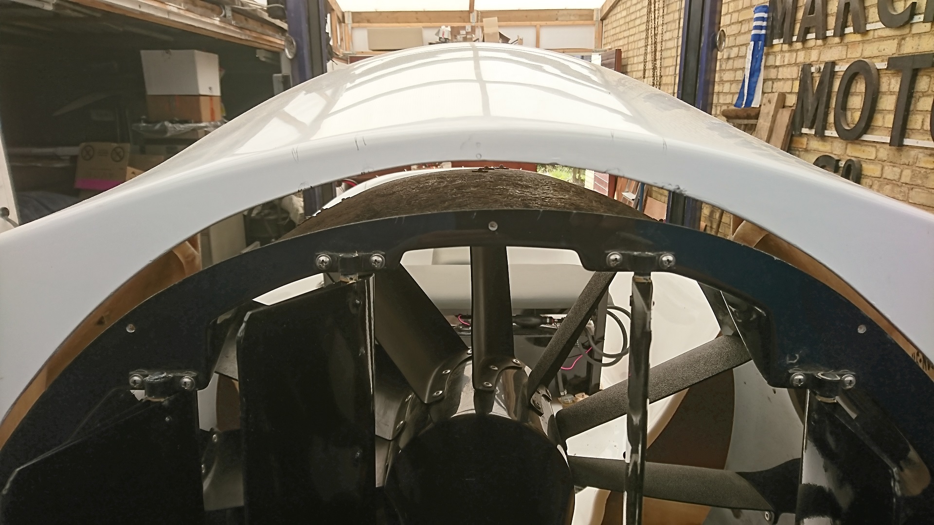
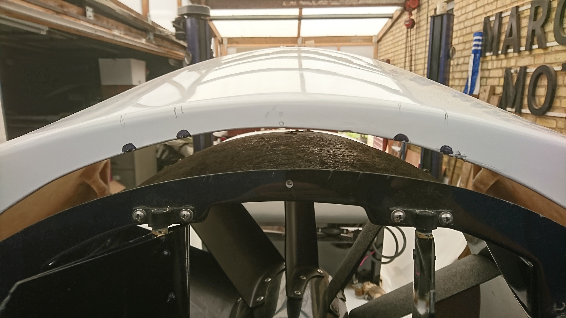
Port Reverse Thrust Duct fitted showing brackets and stabalising, tensioning rod, yet to be ajusted
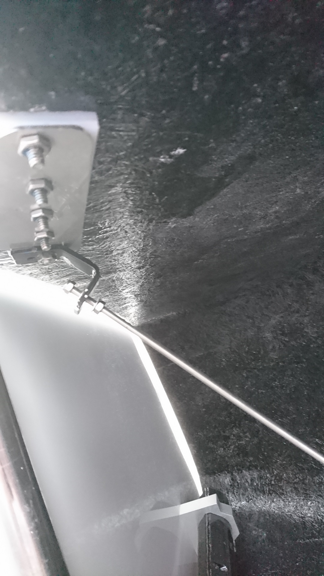
Close up of stainless rod and upper Port bracket
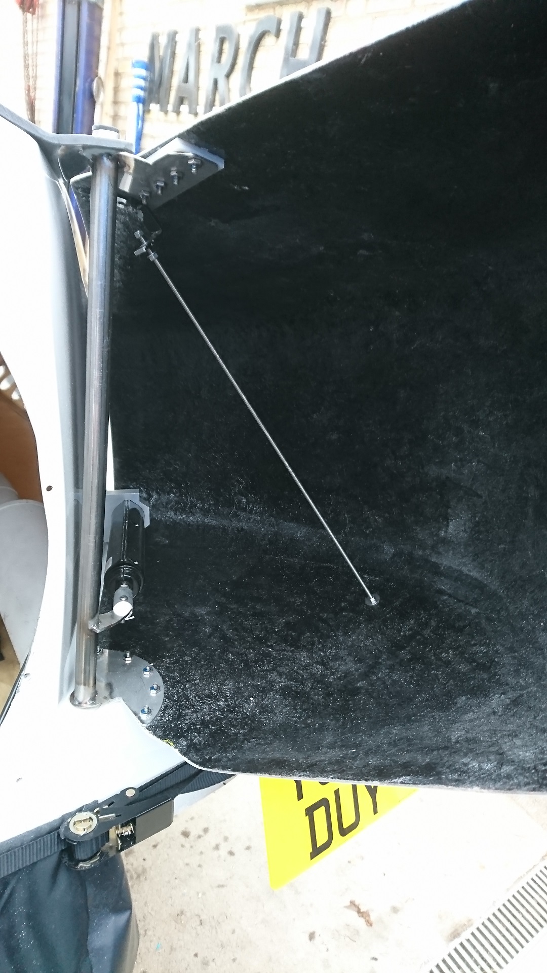
Starboard Reverse Thrust Duct fitted showing brackets and stabalising,tensioning rod,yet to be adjusted
Close up of stainless rod and upper Starboard bracket
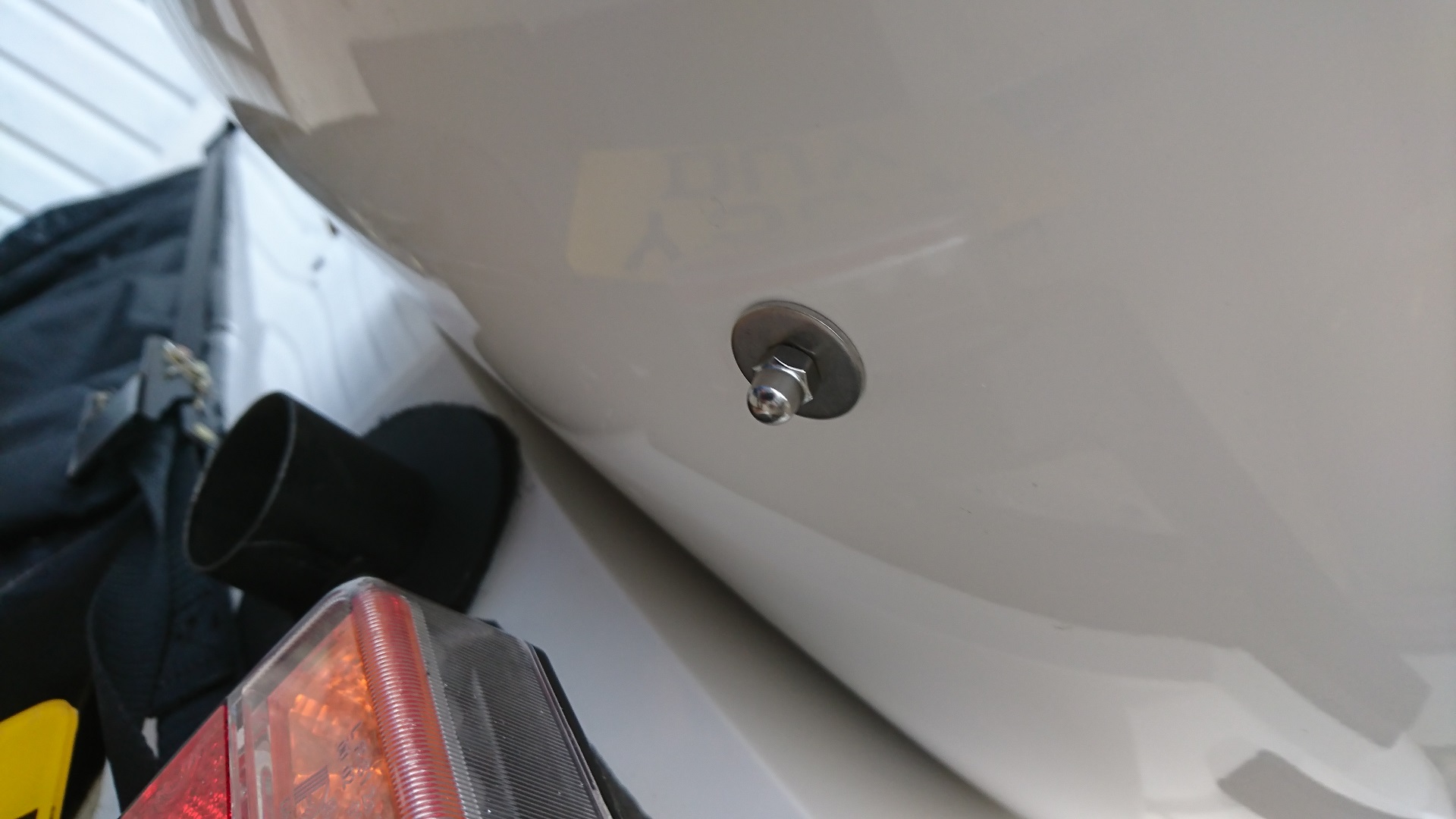
Domed stainless nut and large washer on Starboard Duct(same on Port Dust)
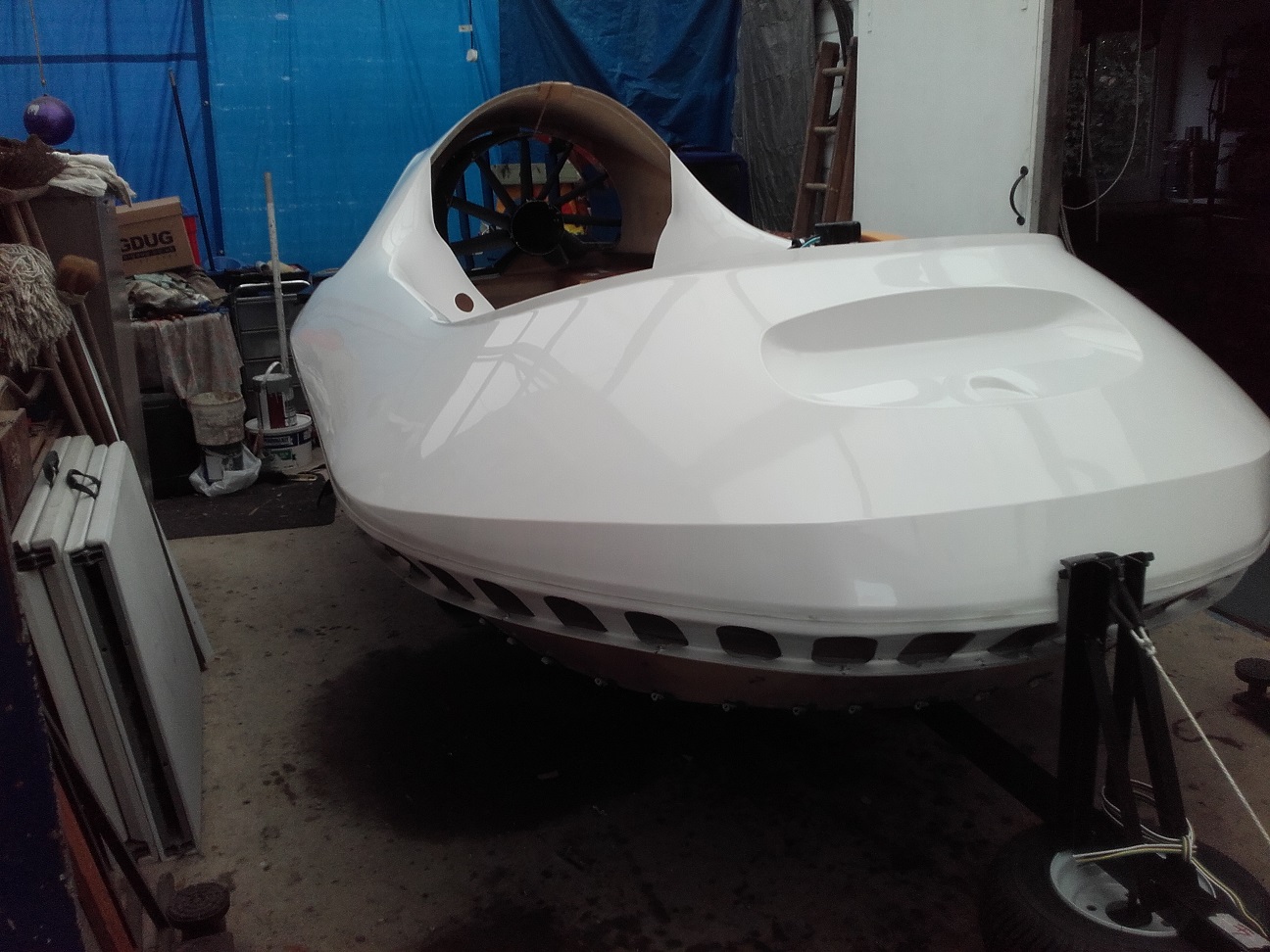
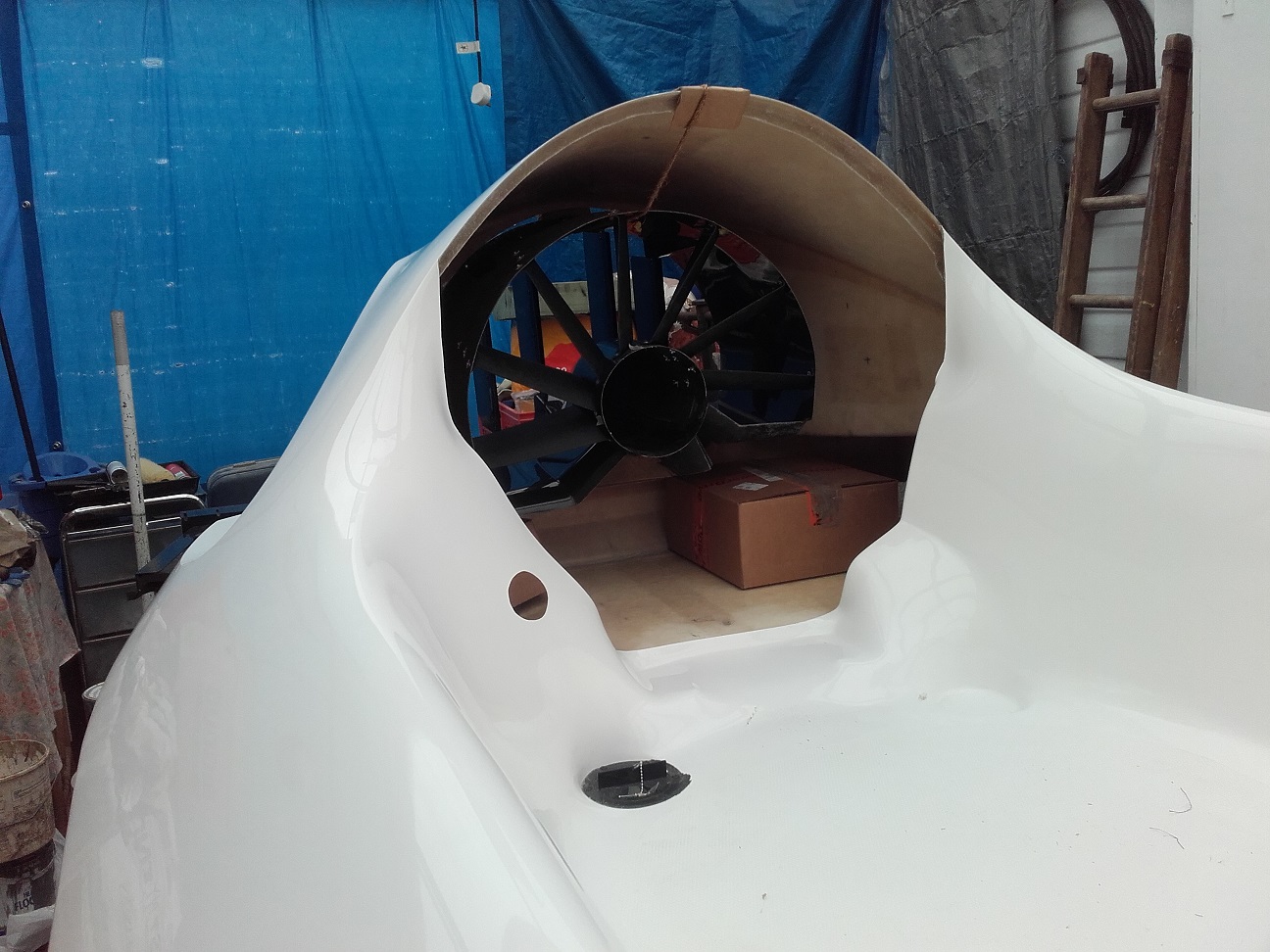
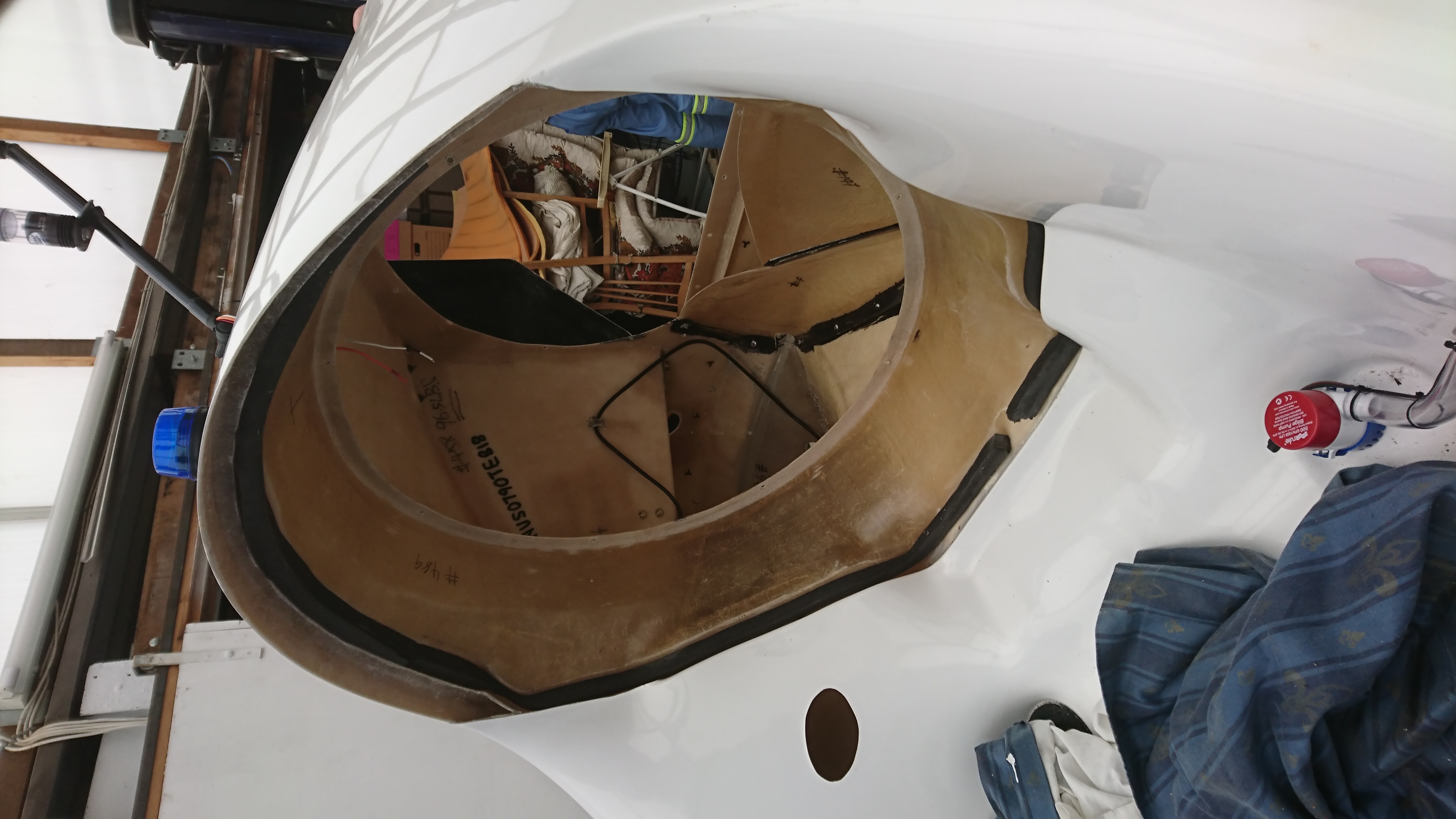
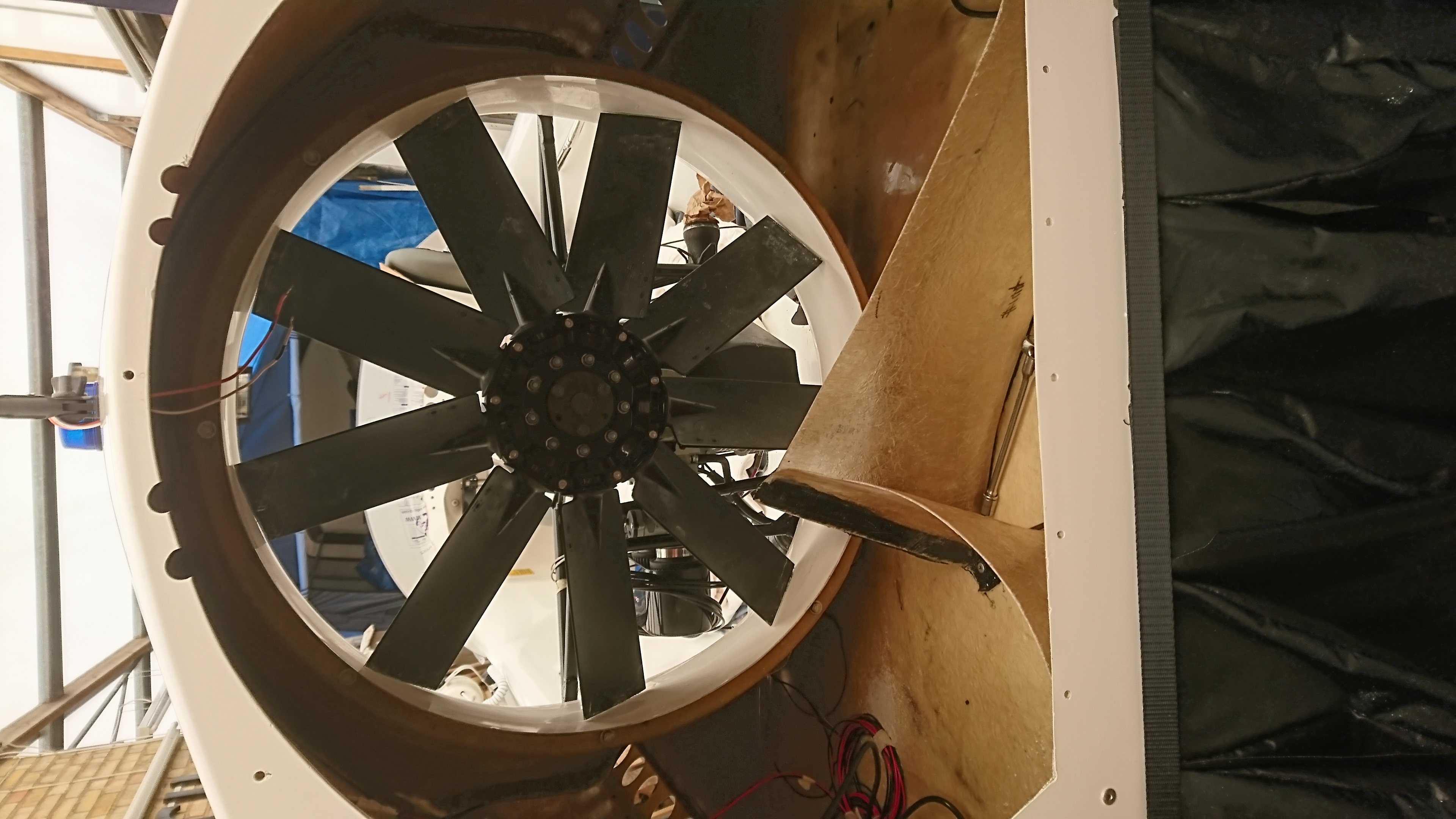
10. Rear Duct and Rudders
It was not obvious how this fitted at first. Photo no. 4 shows just how much has to be filed-out.
Offering up rear duct to mark out for well-nuts
Further marking out of duct position
Rear body filed to clear thrust duct.More to go yet
Now all filed and drilled out
Rear skirt segments and rudder,thrust duct unit fitted
General view of rear taking shape.New rear trailer lights now rewired to UK and European Standard
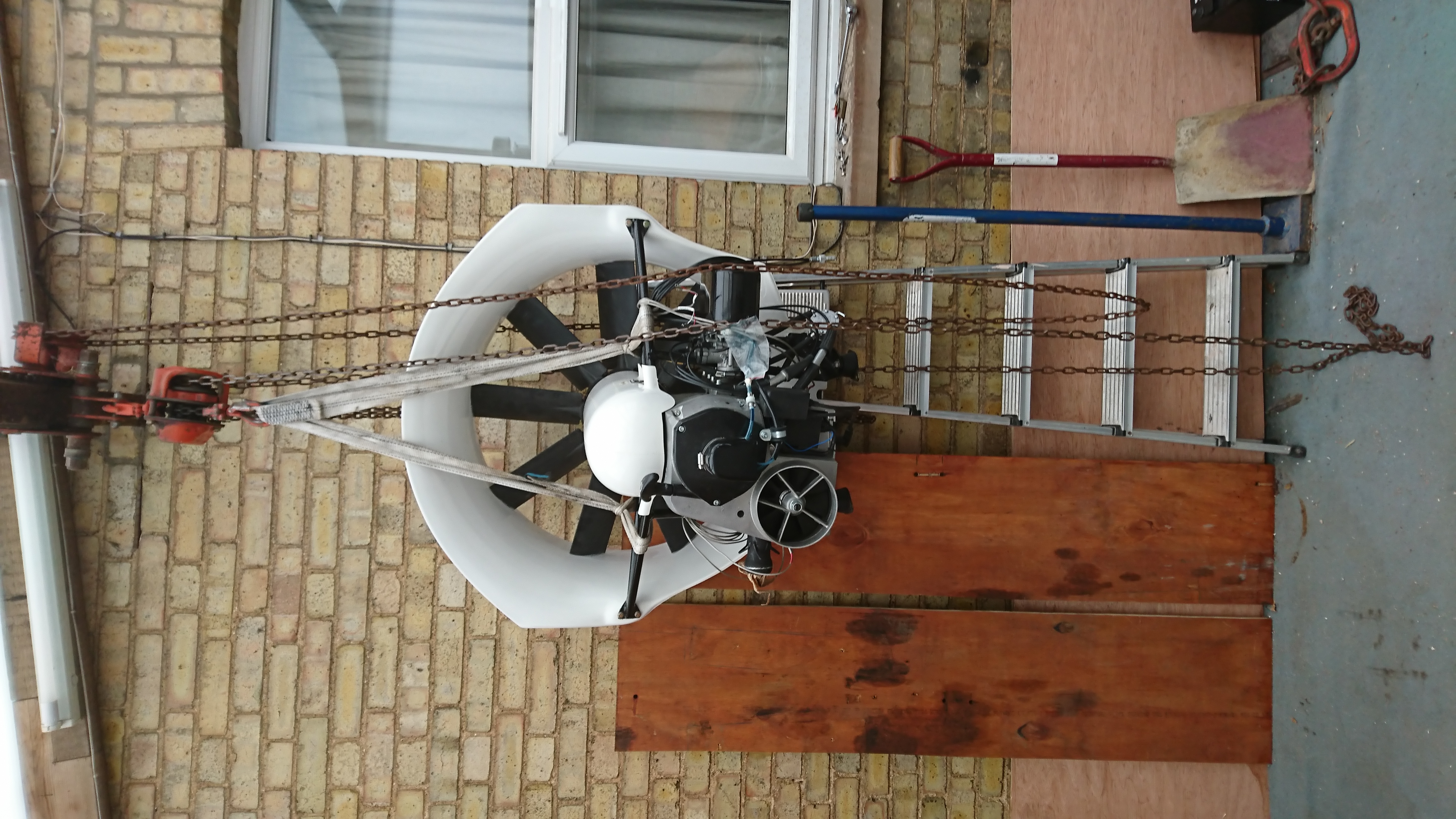
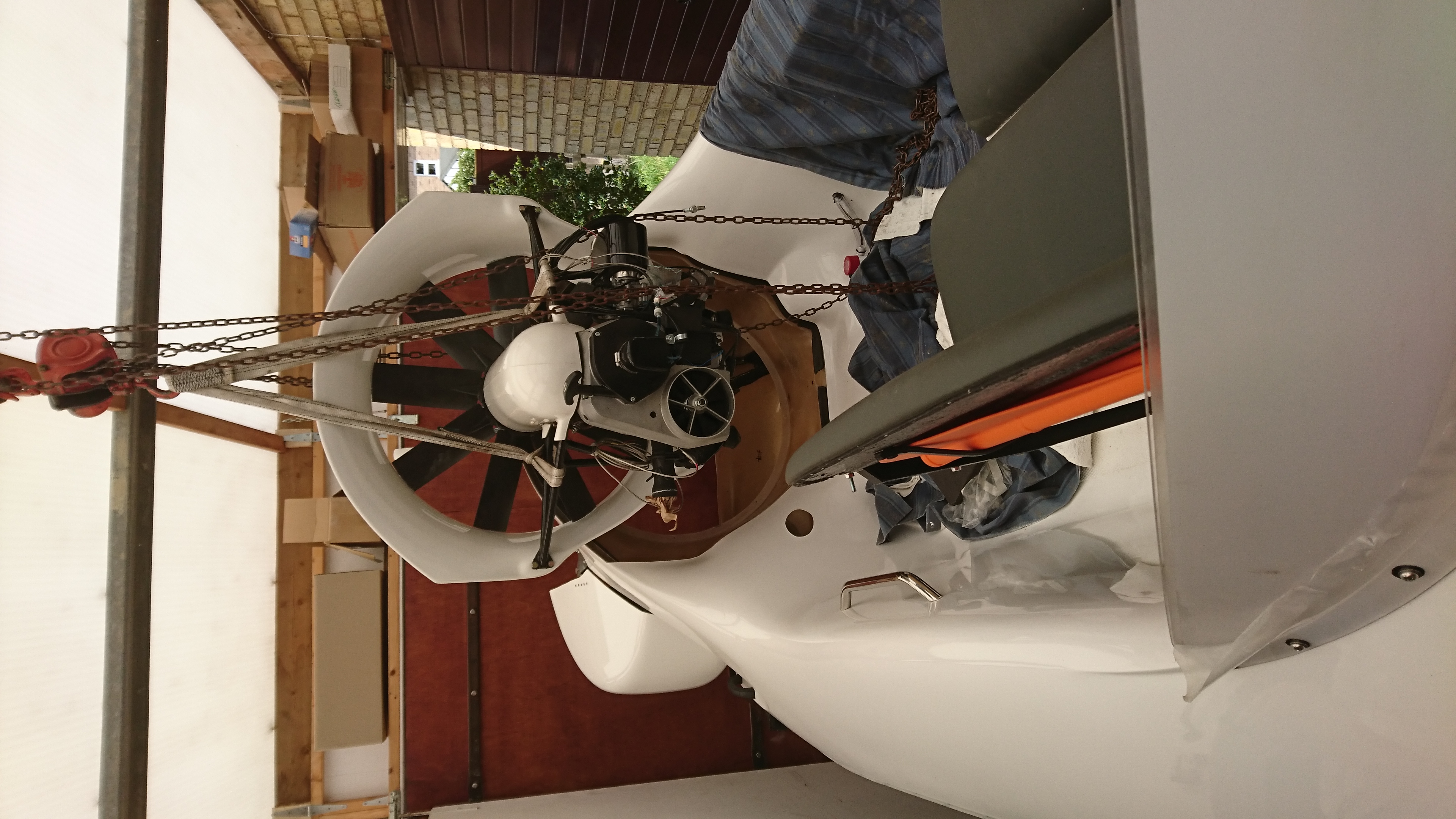
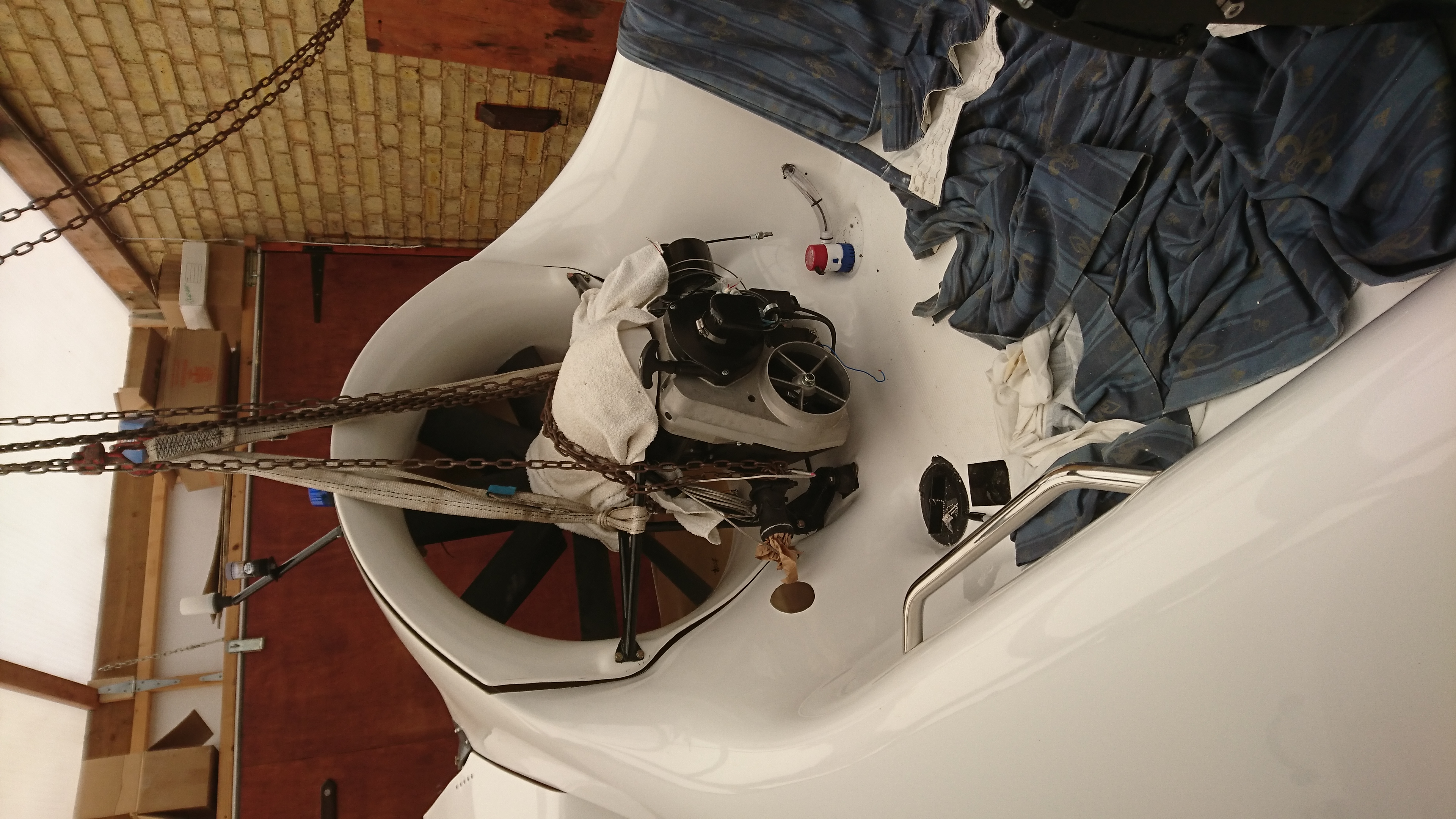
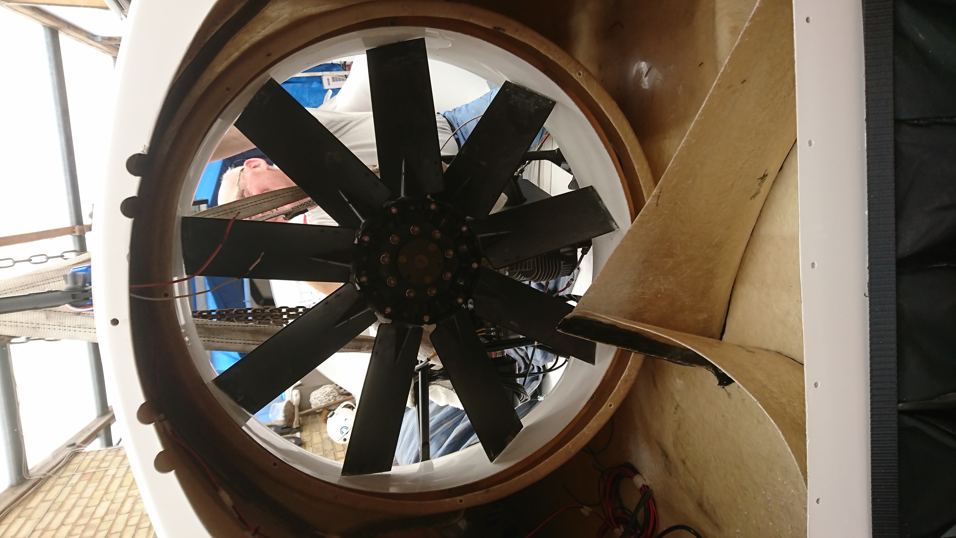
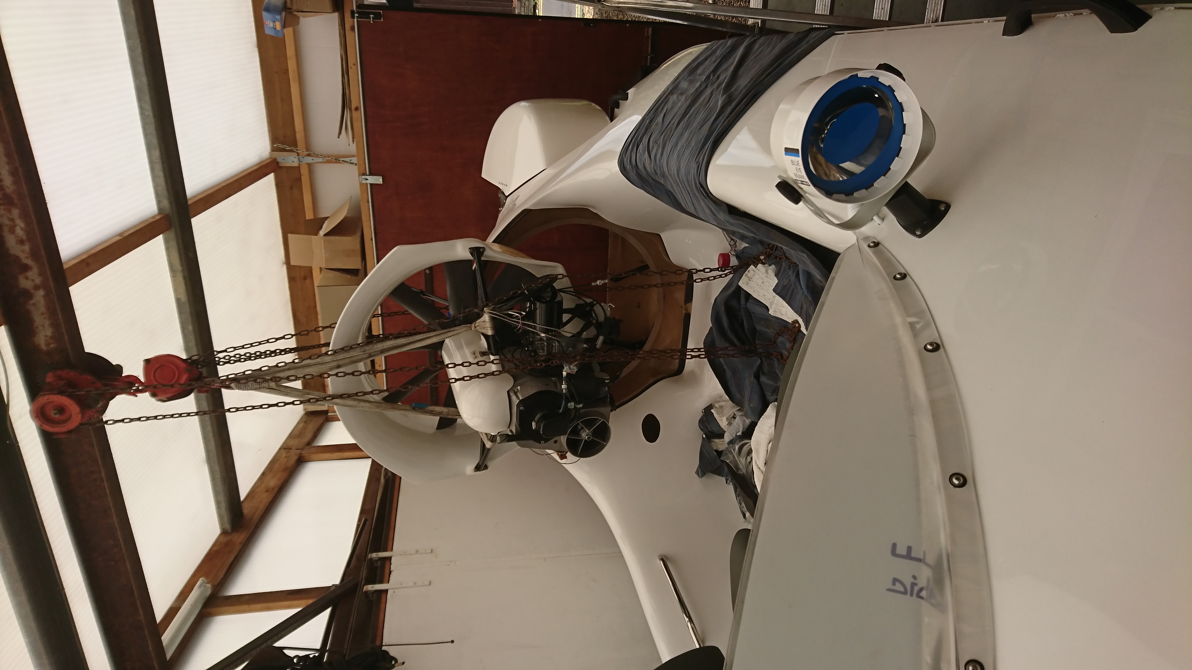
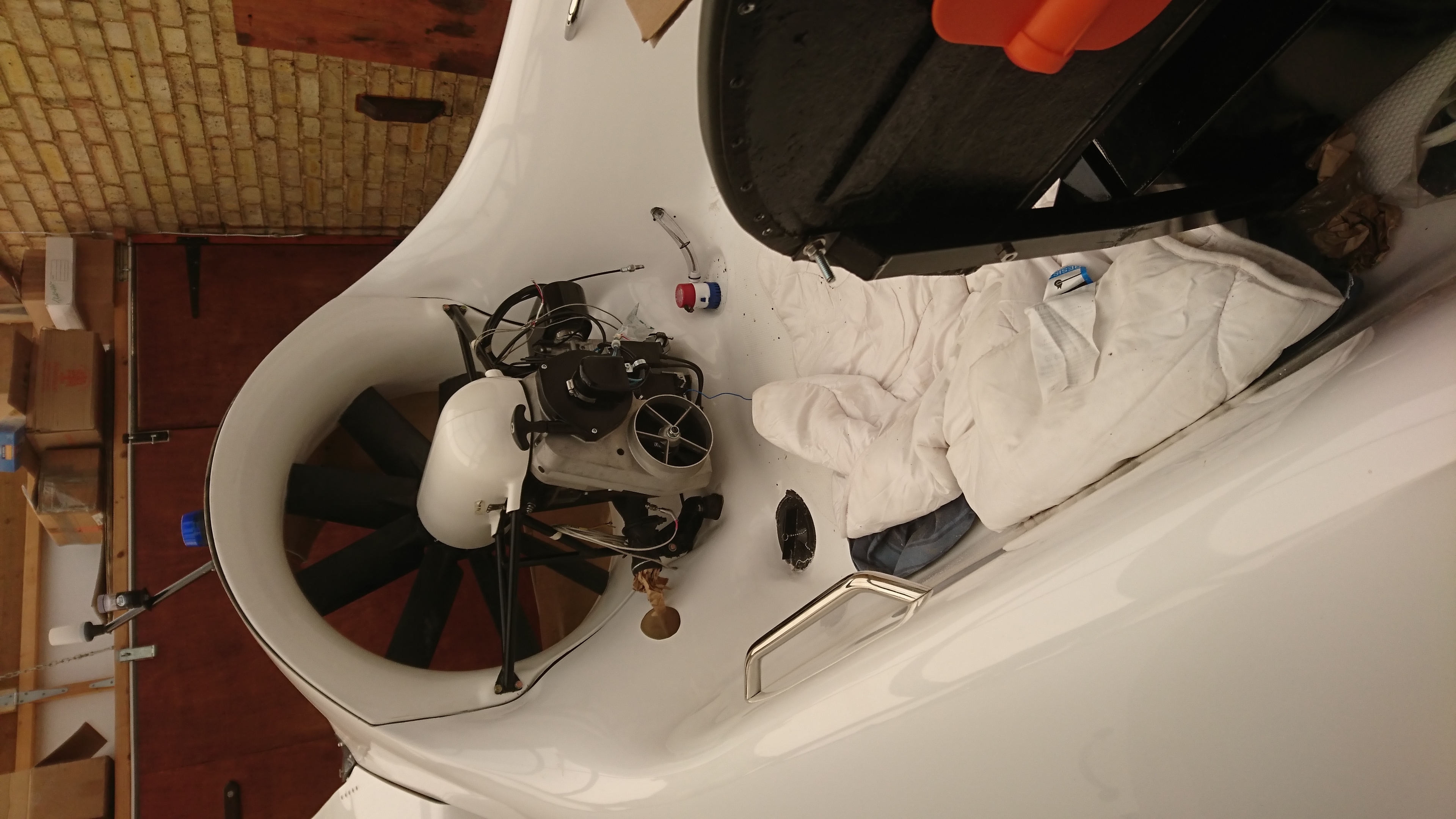
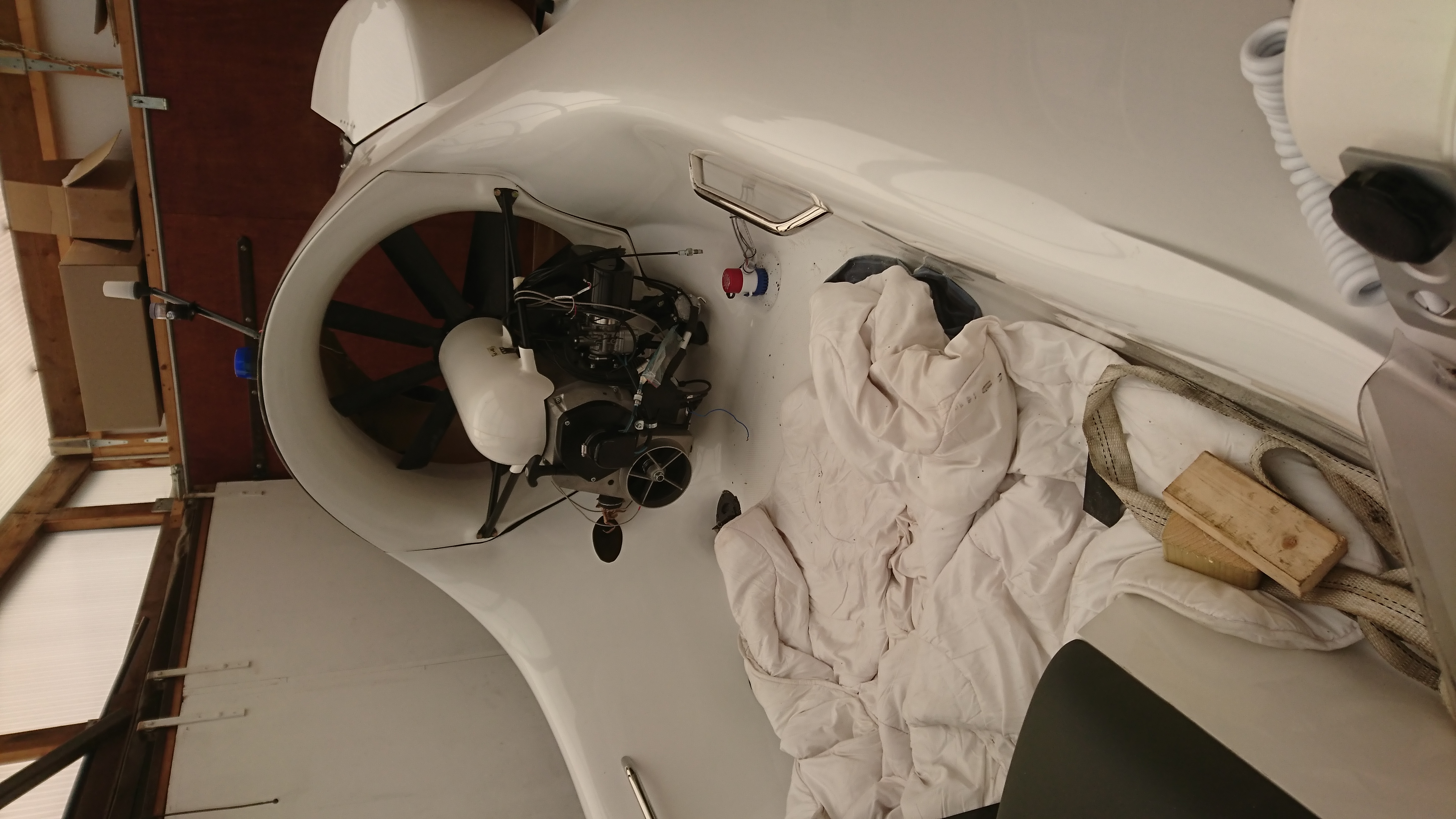
11. Power Unit Fitting
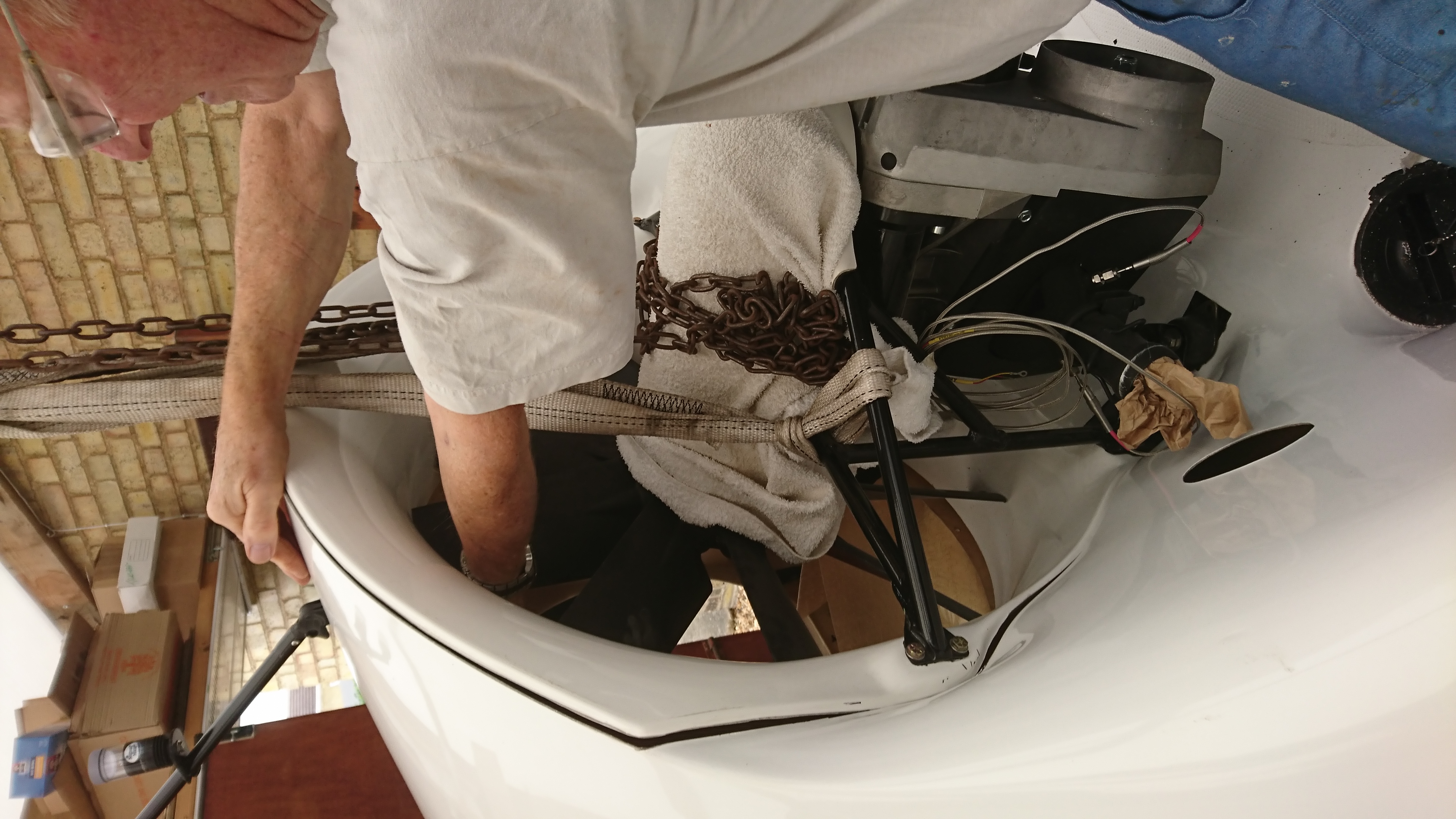
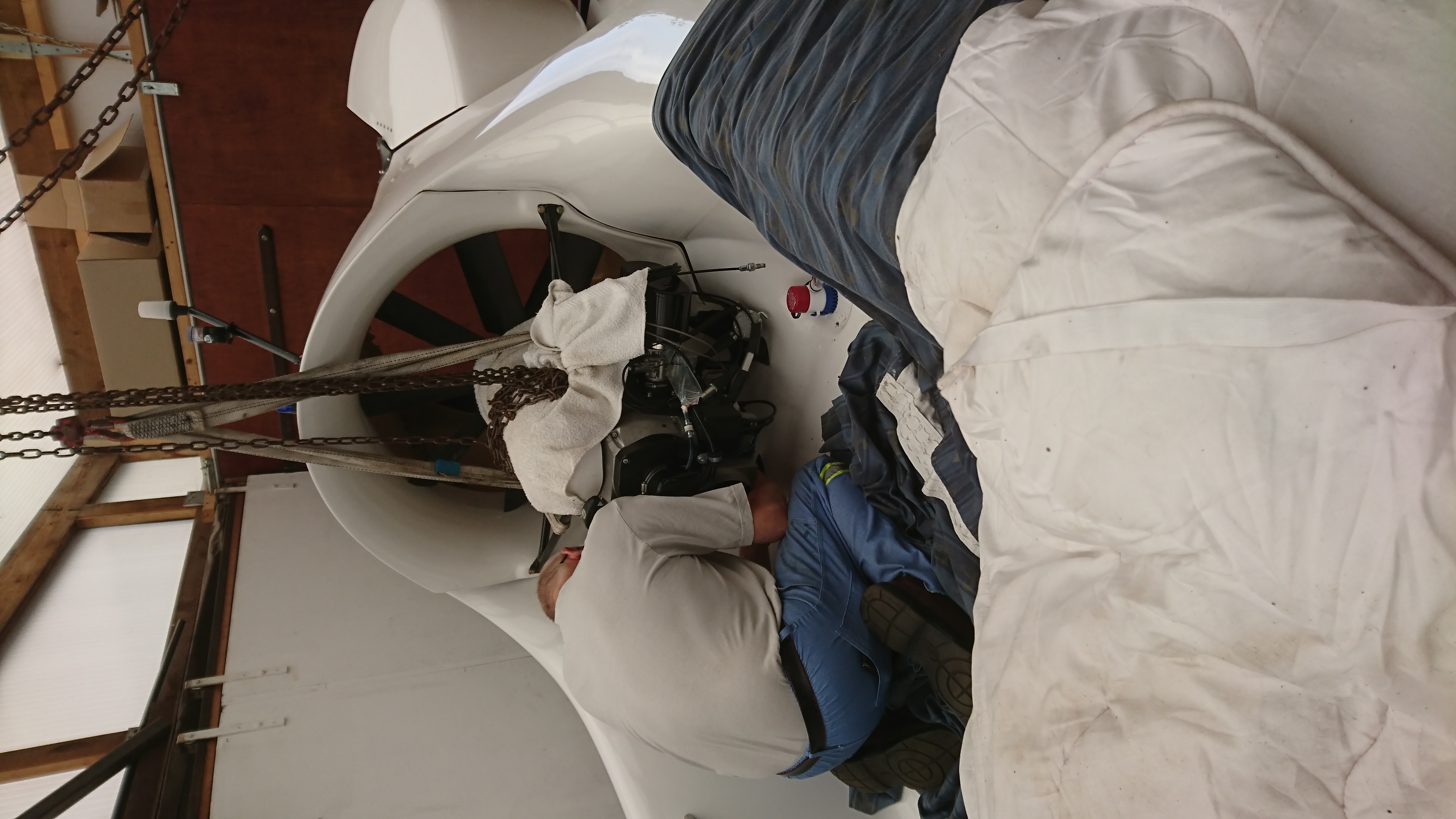
When you see Photos nos. 13 and 14 they look way out. We centered the power unit in the duct and worked from there. I guess with mouldings its very difficult to be exact. We worked on the centre line of the engine and the middle of the duct. There may have been some discrepancy with the engine framework too, but it all works!
Power unit suspended on overhead crane ready for installation
Rear body having had thrust duct fitted and checked with splitter plate. Craft turned round ready for fitting power unit
Ready to offer power unit to mark engine mounting position bolt holes
On the way in. Just stabalized the craft so we can climb in safely
Lining up power unit in housing in preparation for marking and drilling holes
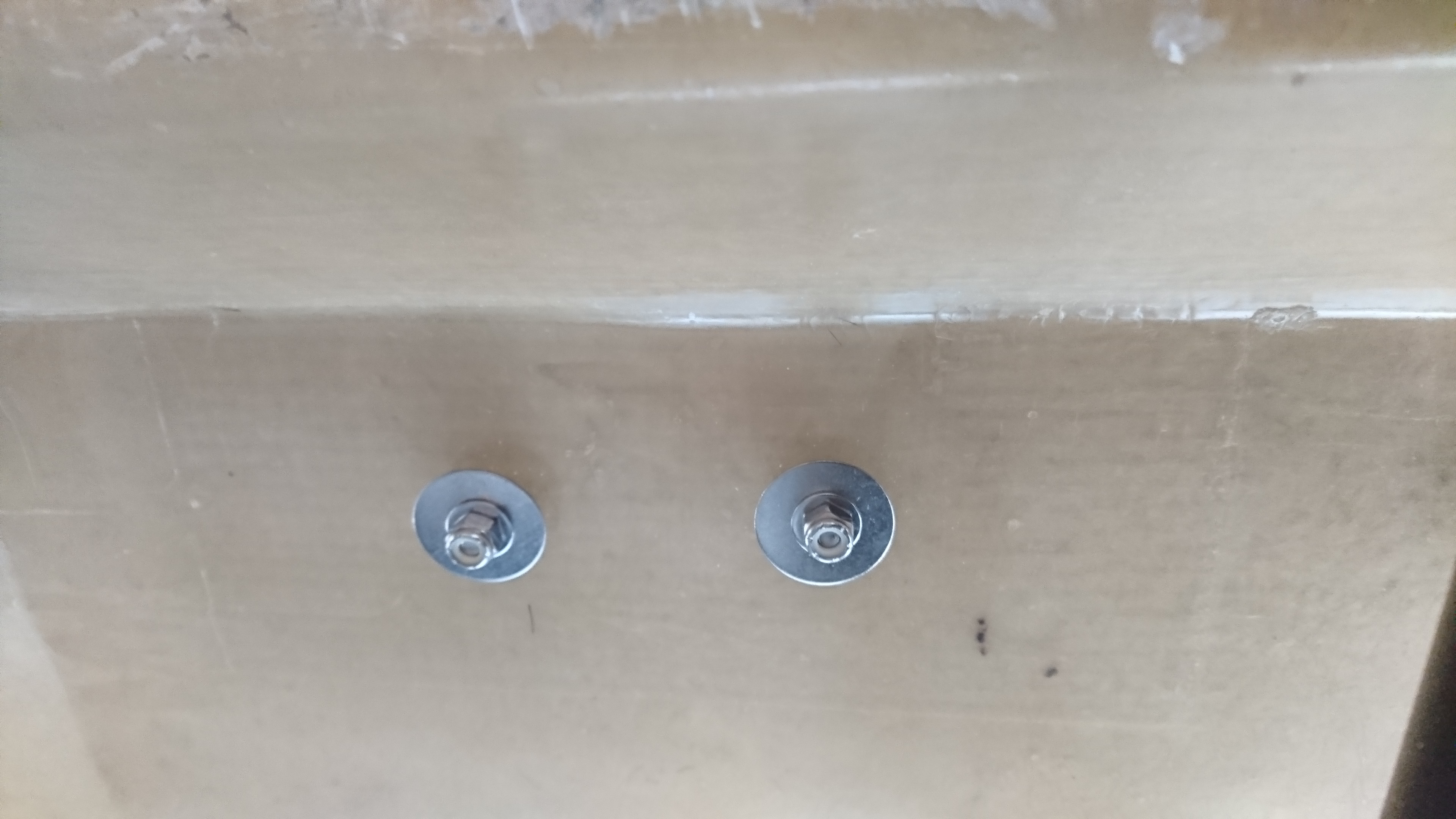
Engine mounting Starboard side
Engine mounting Port side
Engine mountings from above
Another view of power unit going in
Dave getting the packing in the right place
Dave fitting the engine mounting bolts with me underneath putting the nuts and washers on
Port Engine mounting from below
Starboard Engine mounting from below
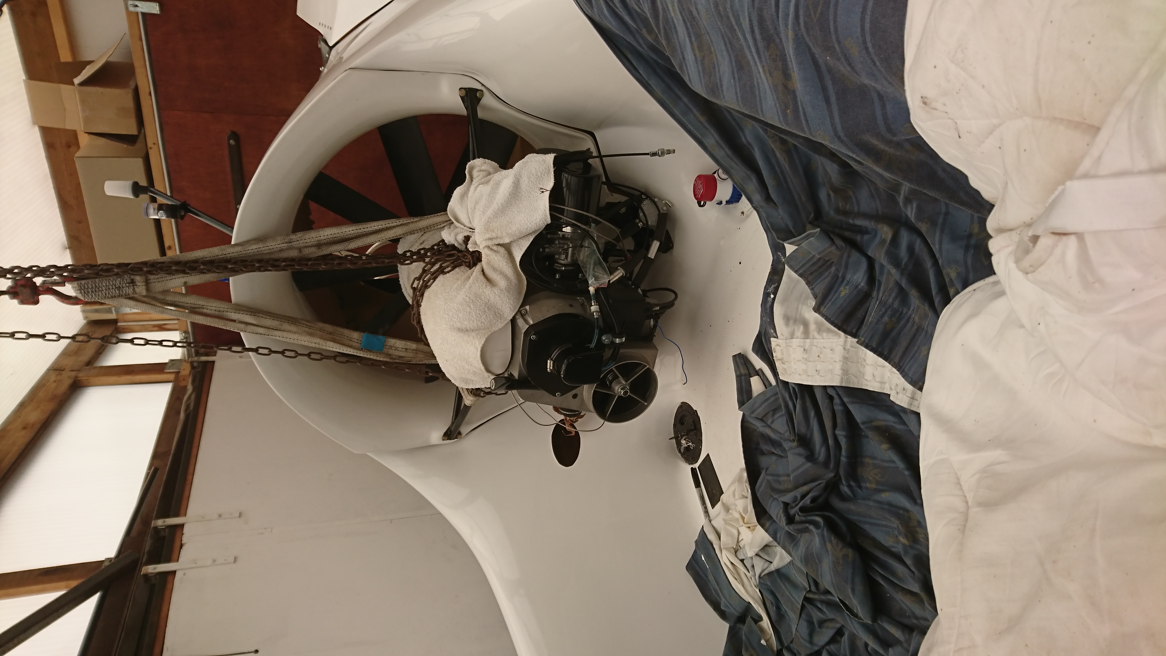
About to take off the lifting strops
Another view of Power Unit with overhead crane now away
Power Unit now with overhead crane off
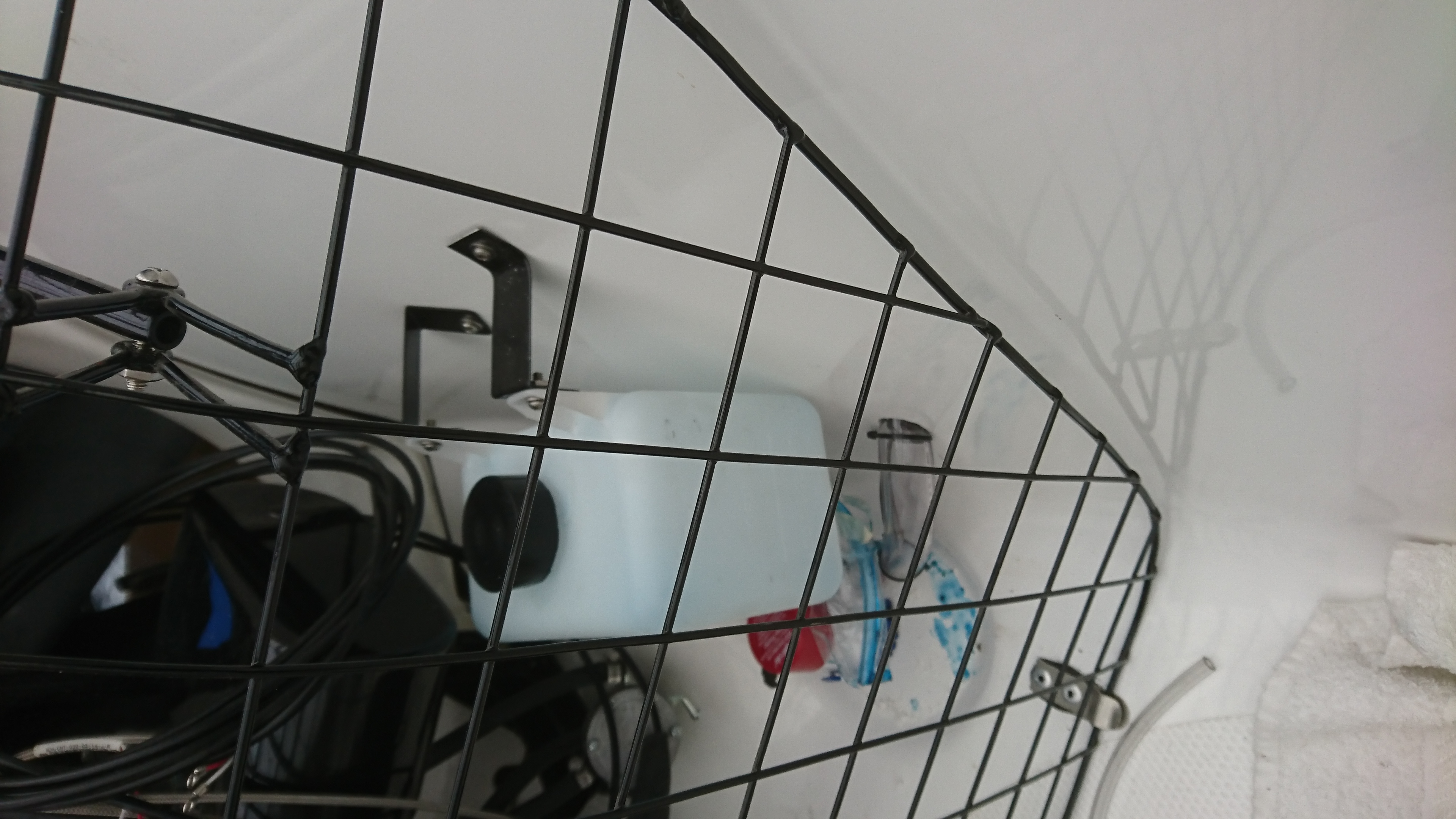
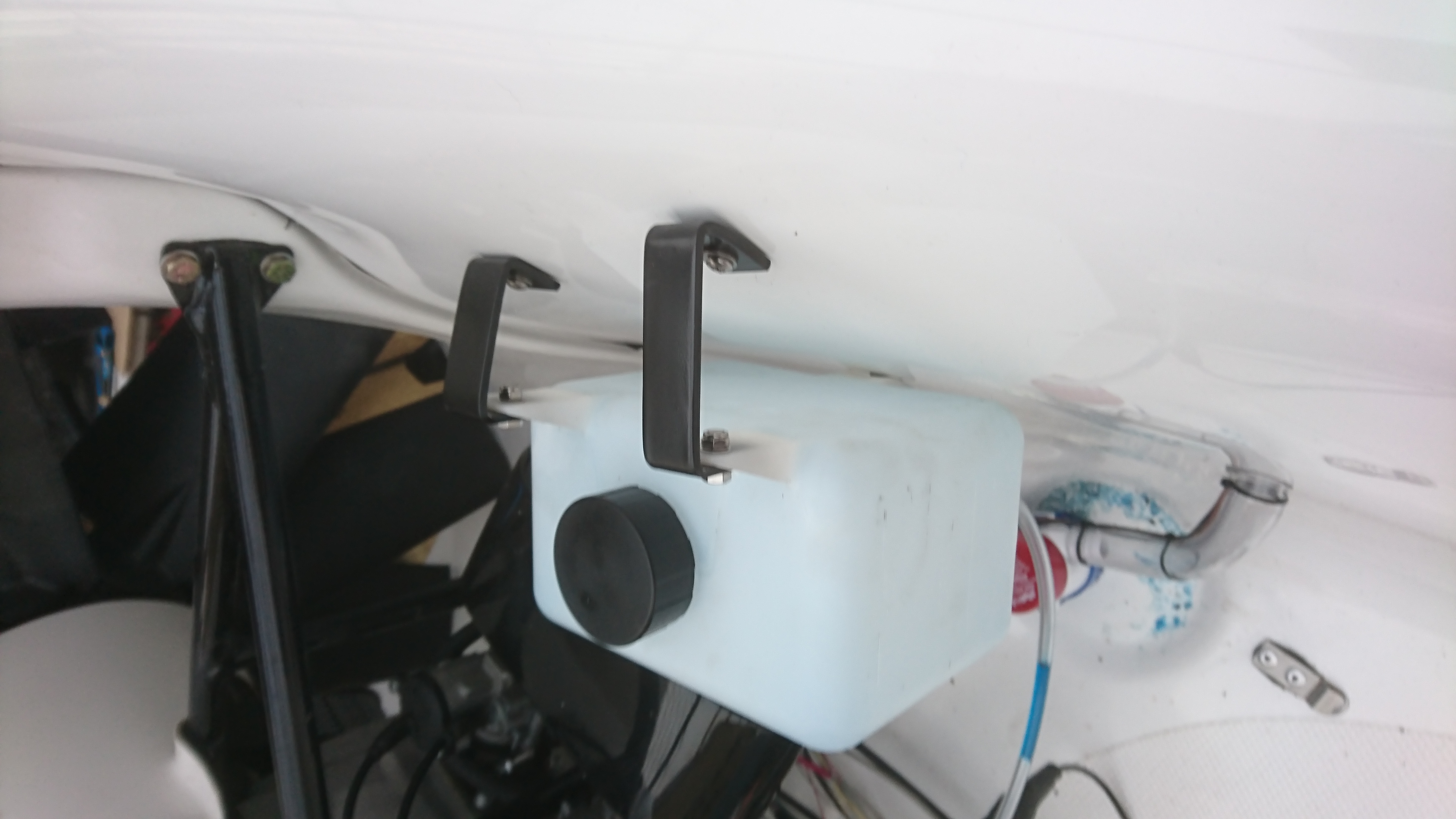
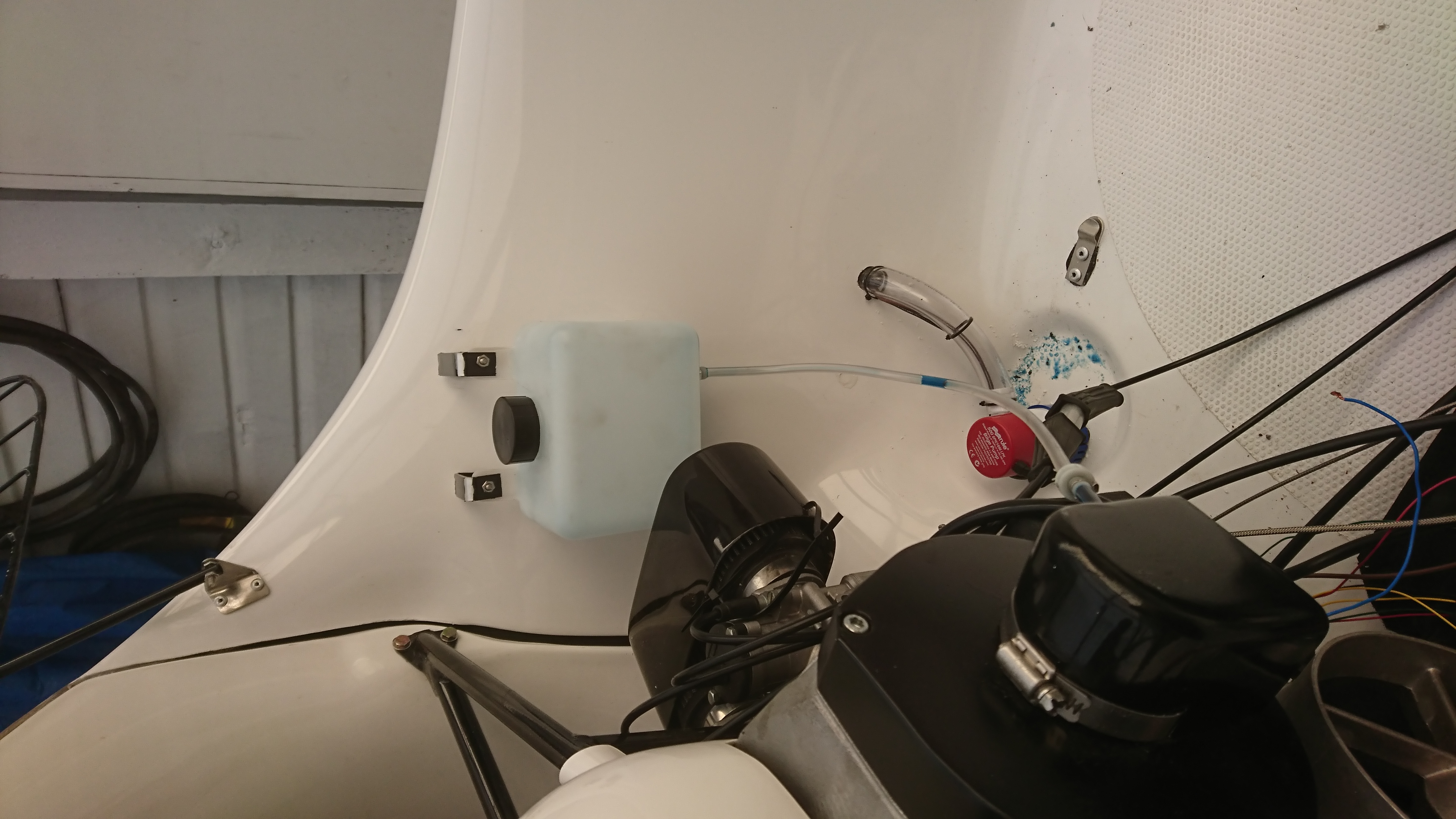
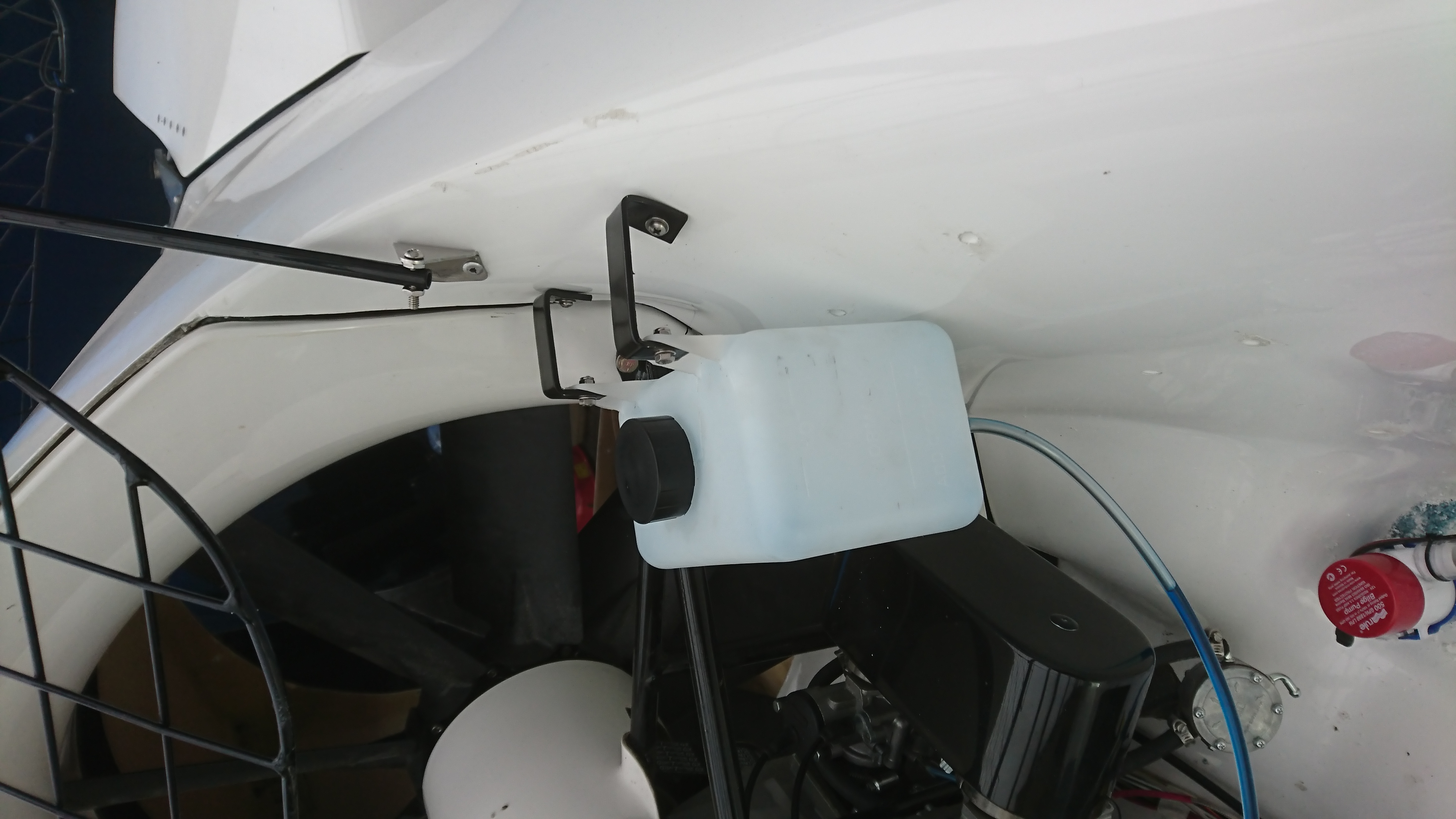
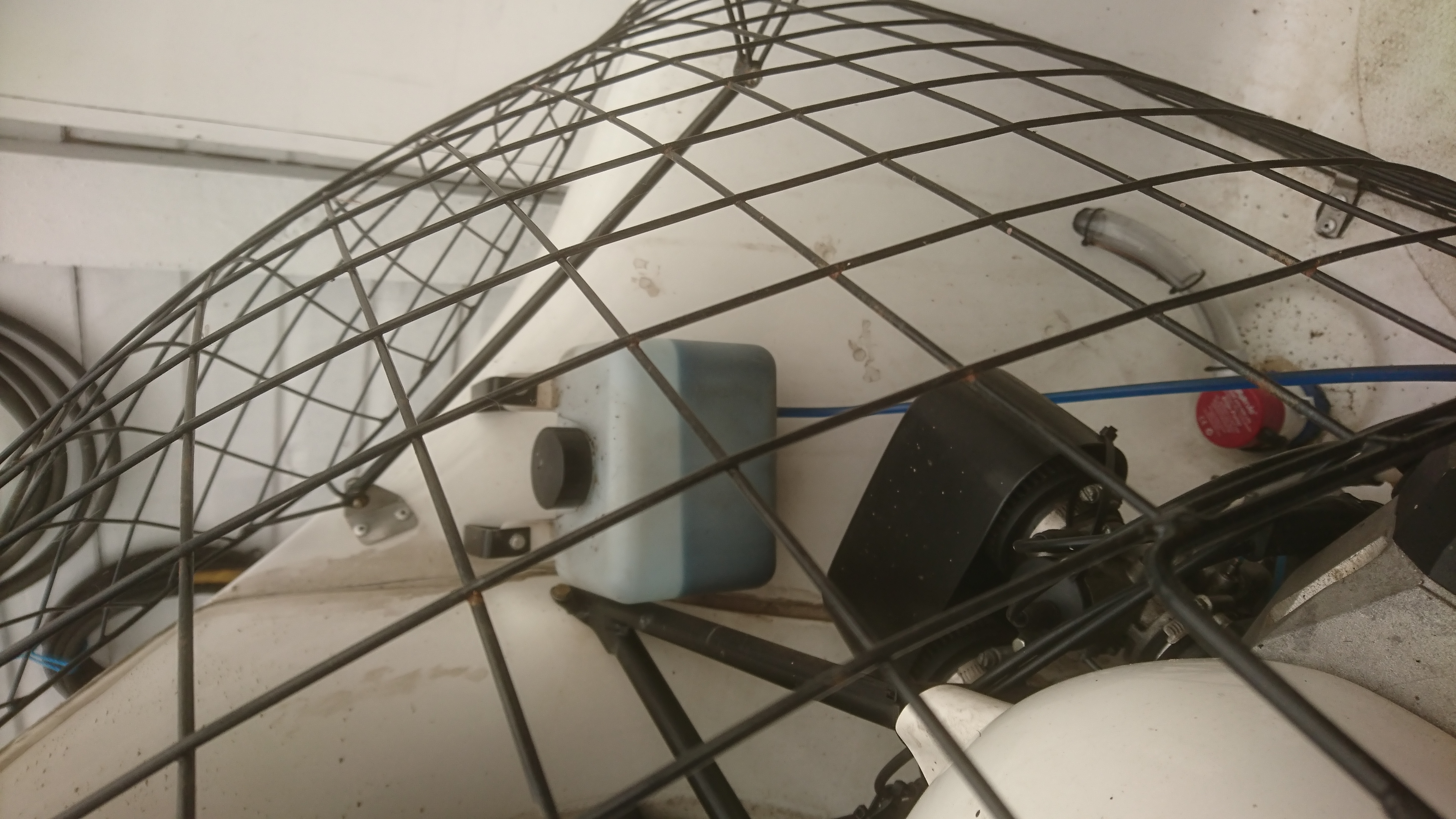
12. Oil Tank
Original instruction was wrong. Only when told the bottom of the tank needs to be level with the pump, did we get it right.
Oil Tank in wrong place (too low)
2nd position of Oil Tank (Wrong, too low)
3rd position of Oil Tank (Wrong,also too low)
Final correct place and height for Oil Tank
Final correct place and height for Oil Tank
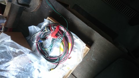
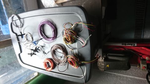
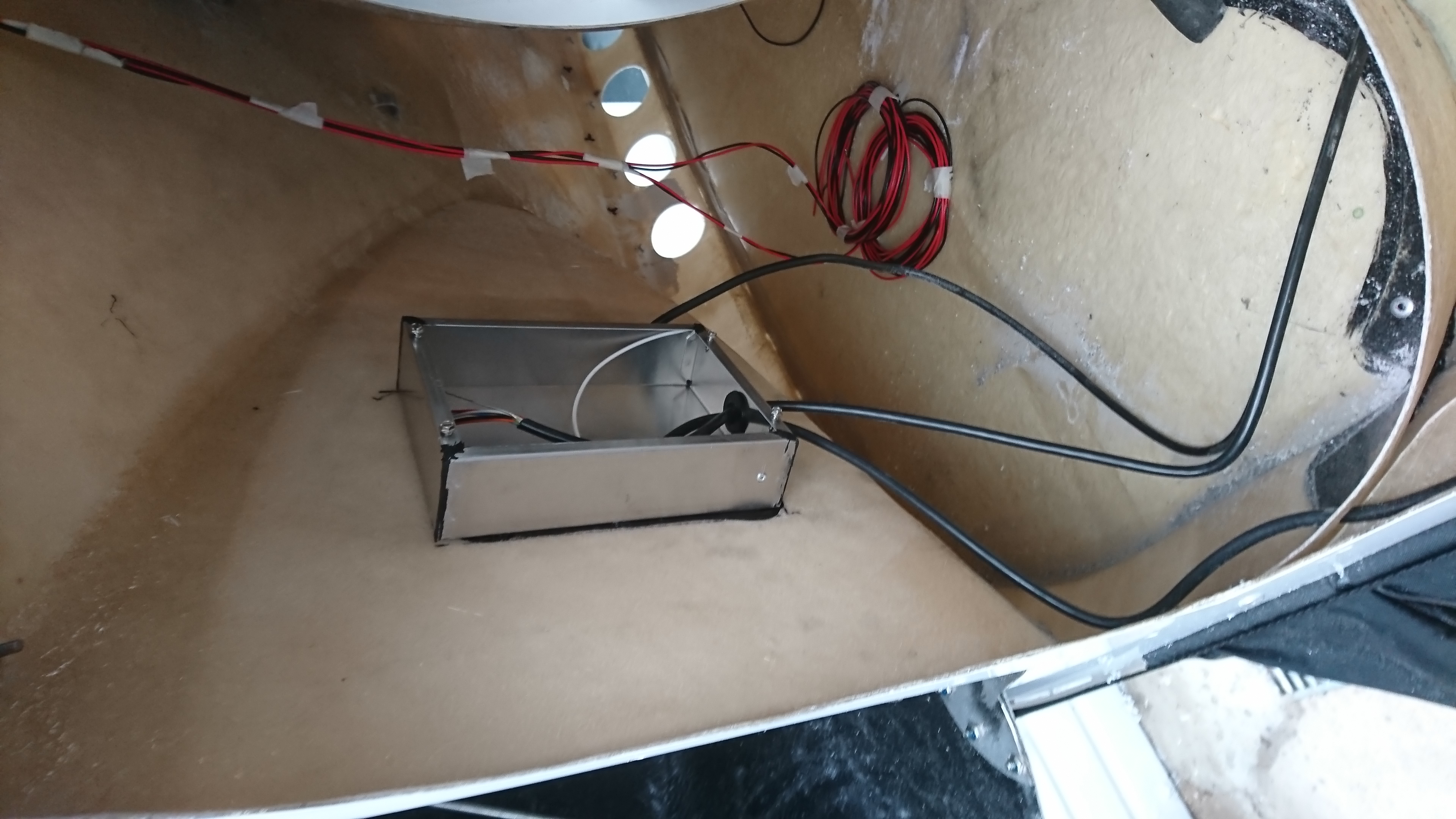
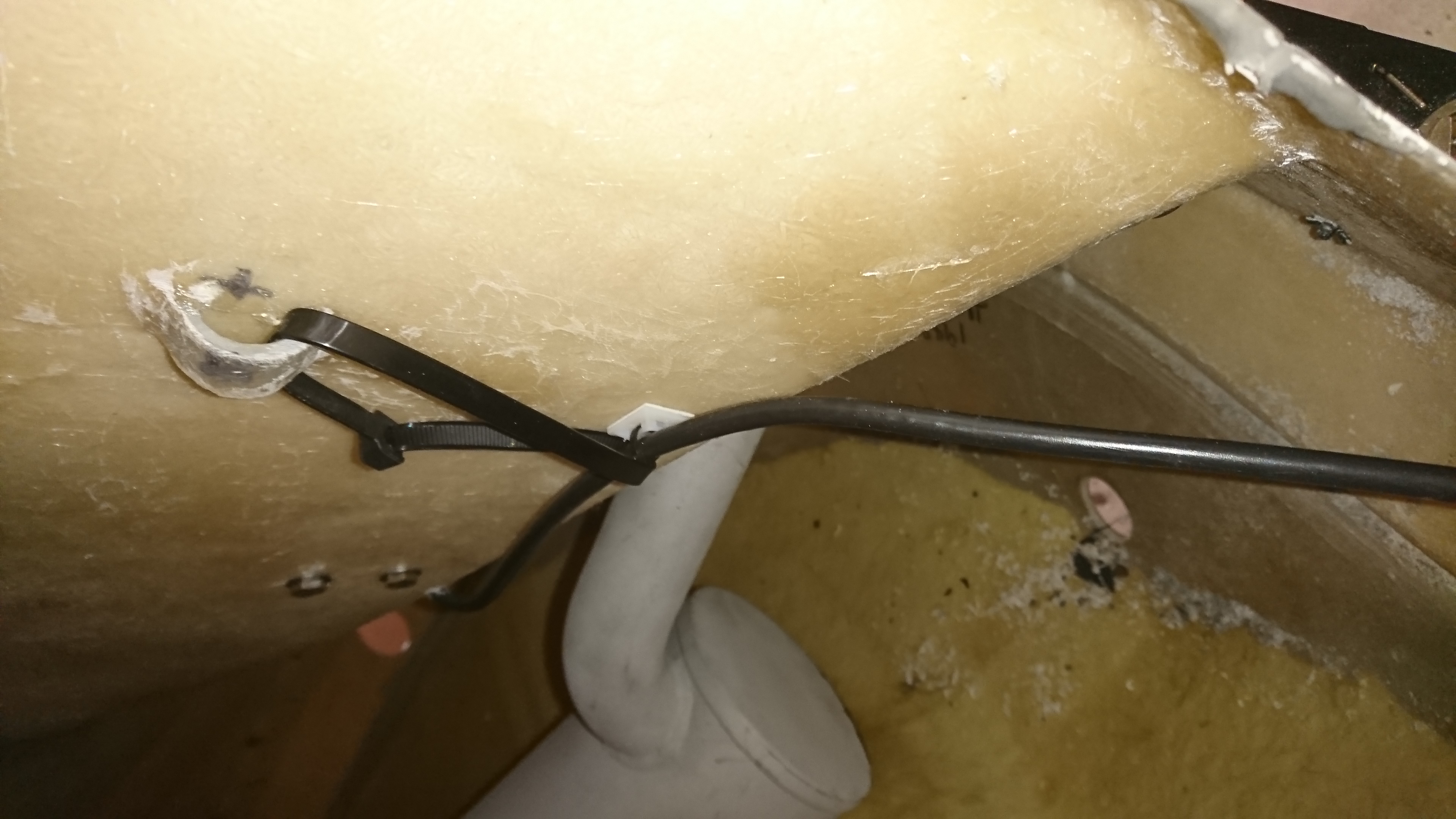
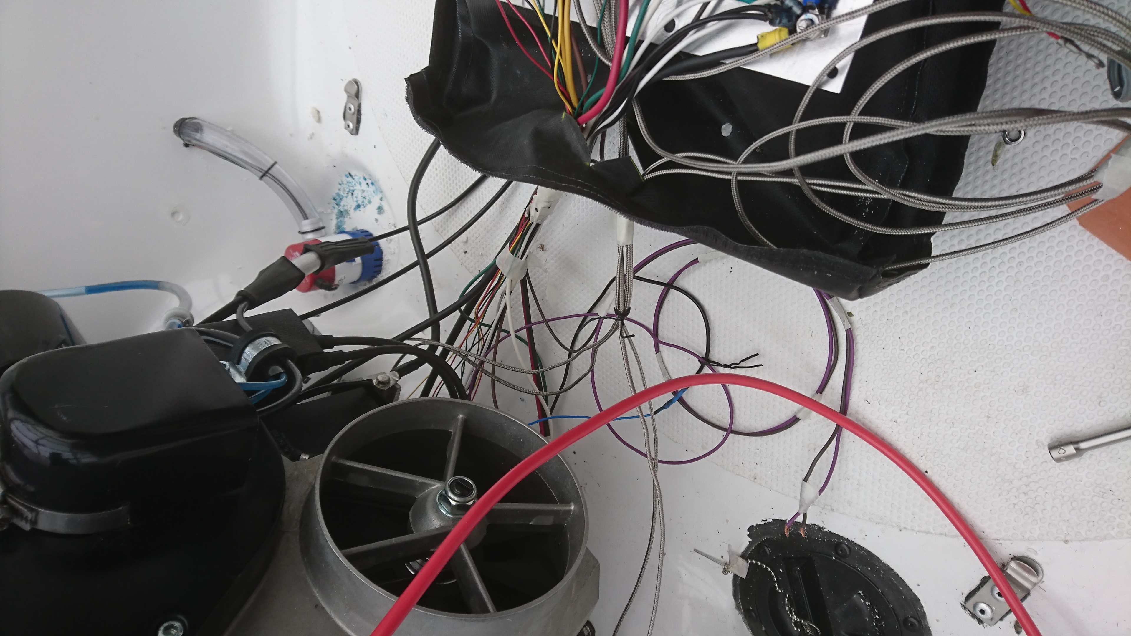
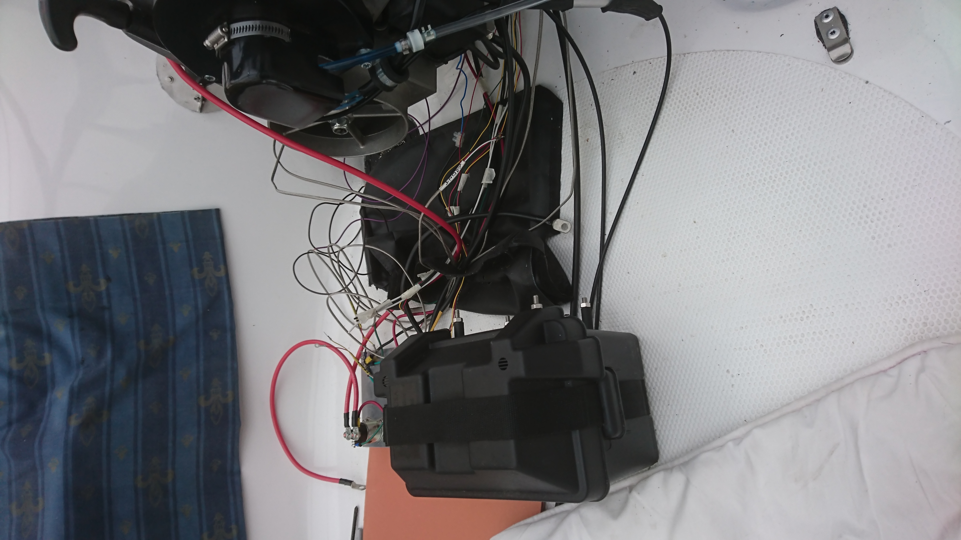
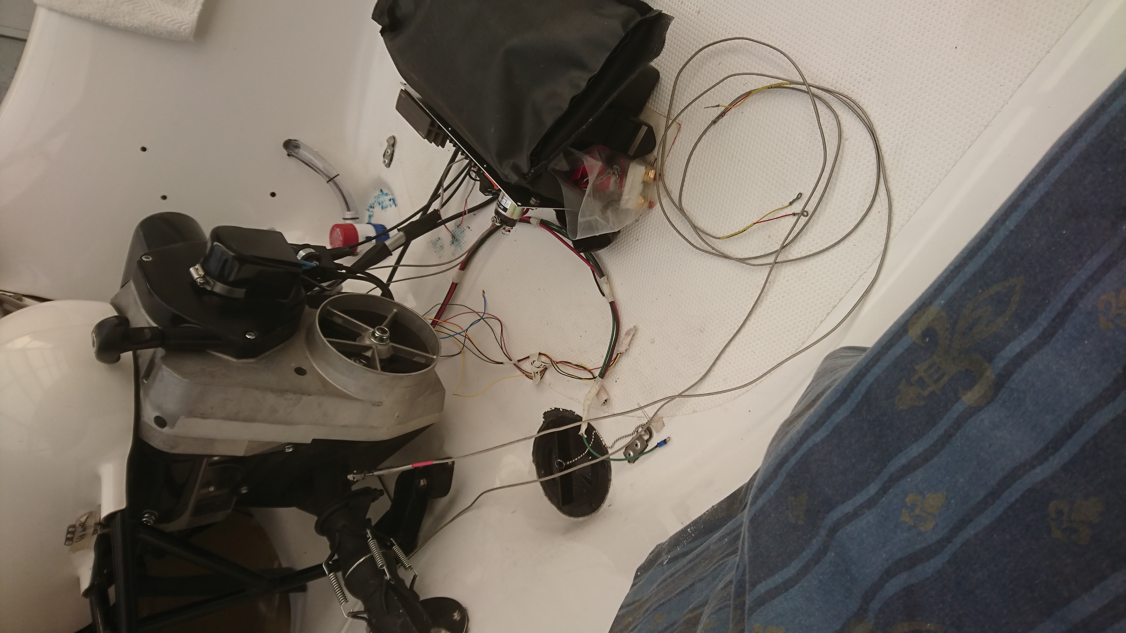
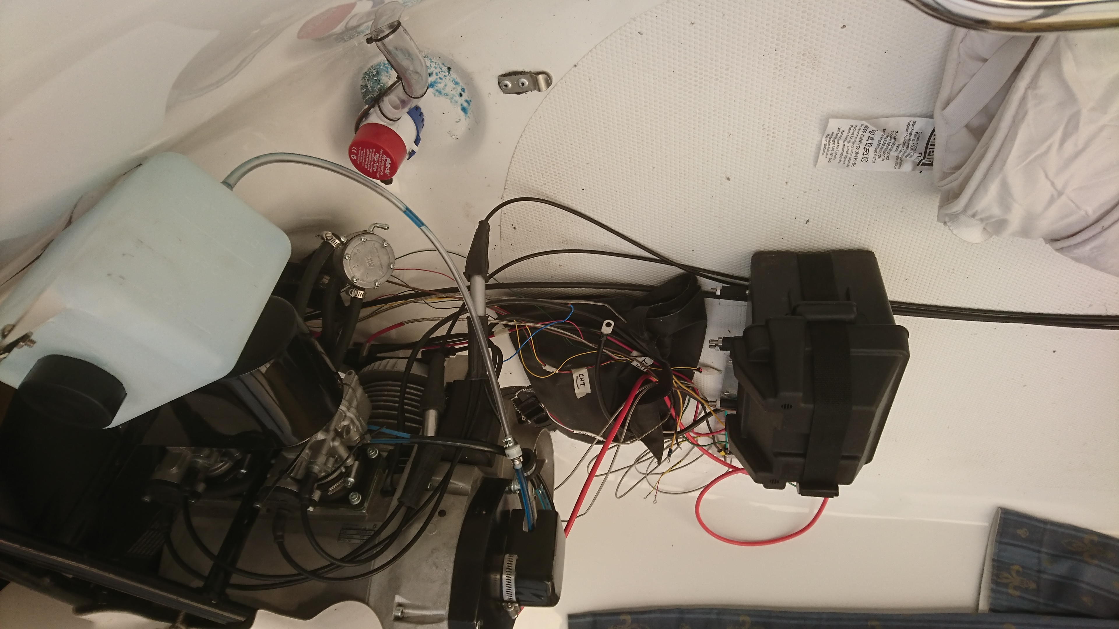
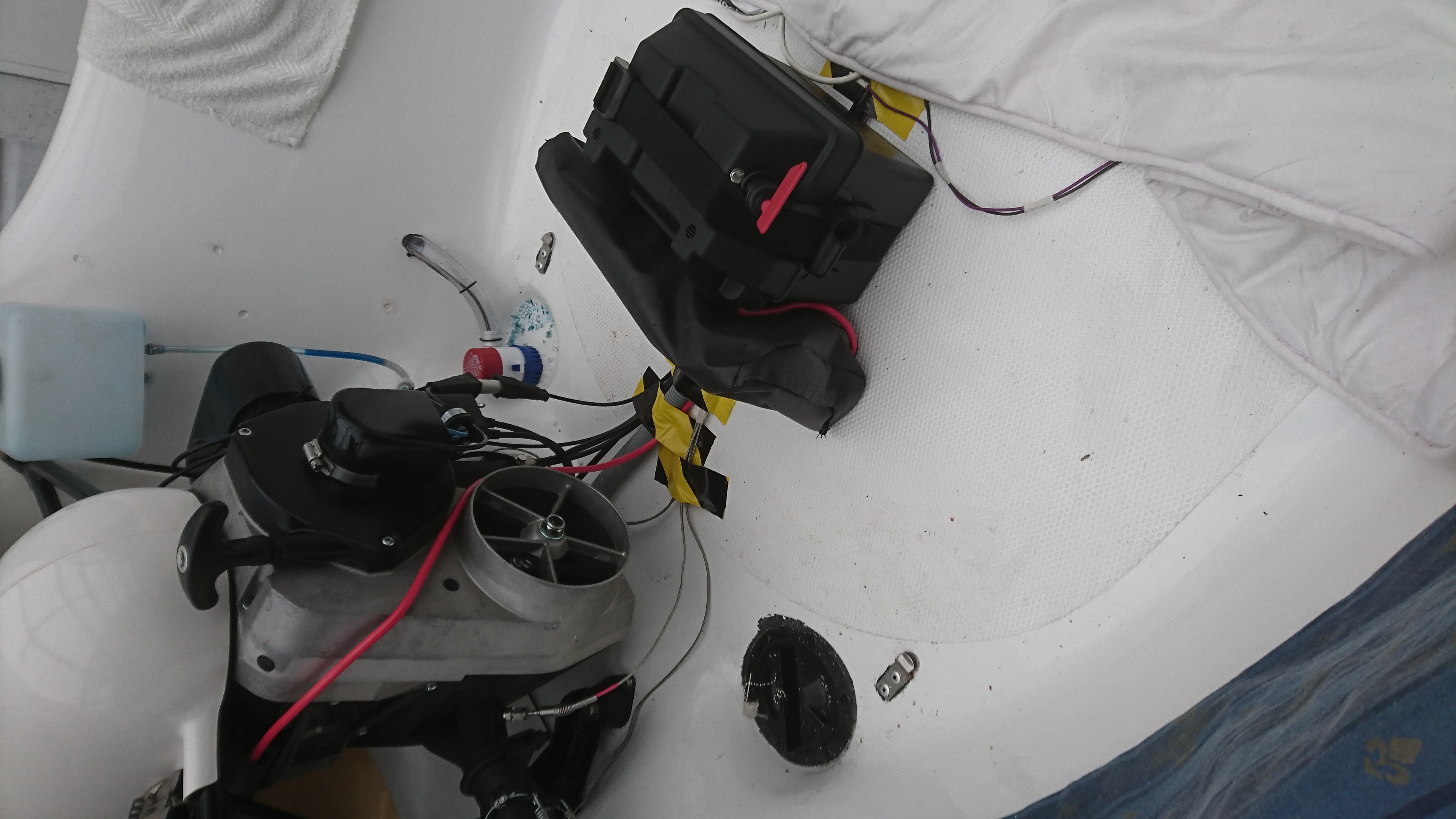
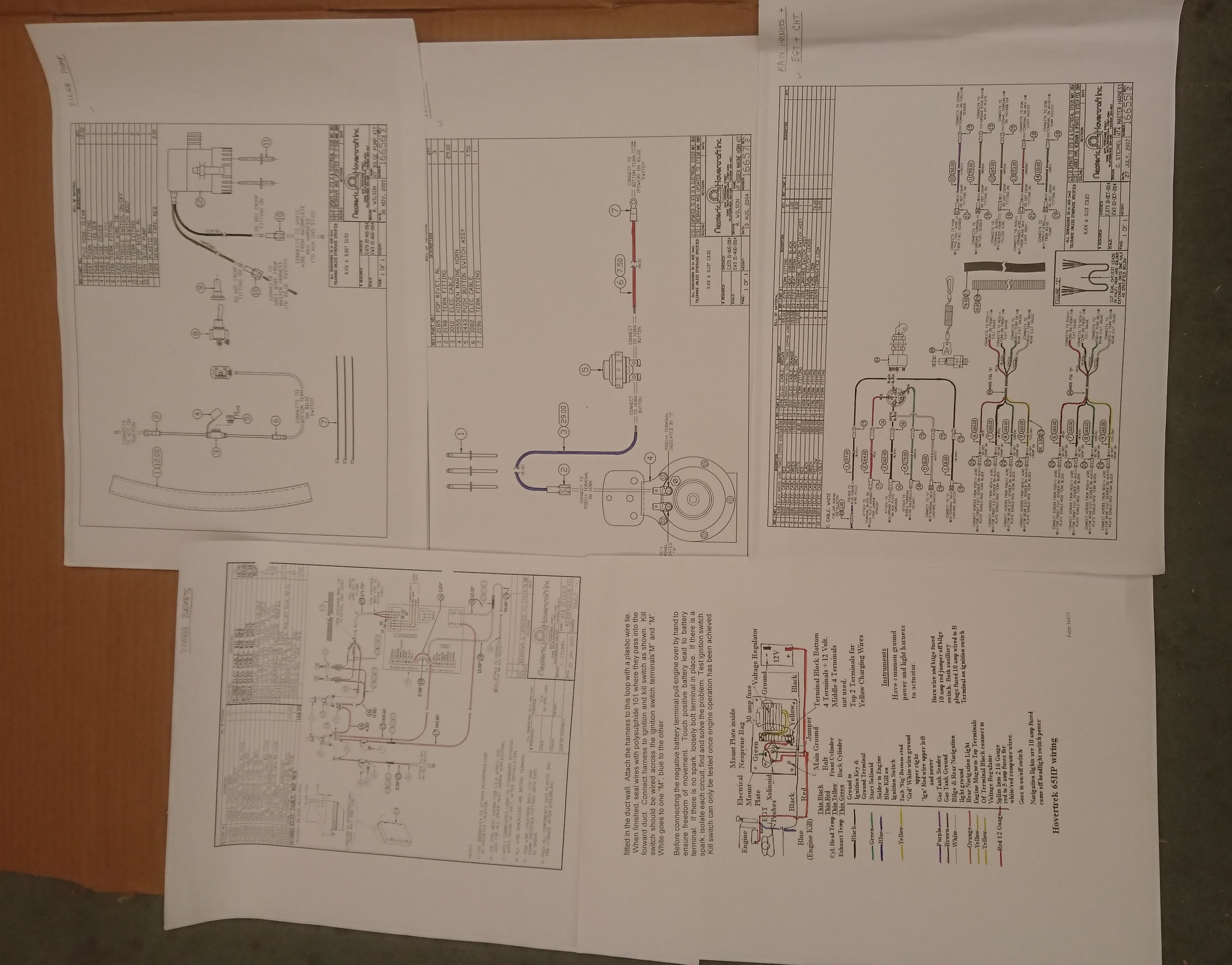
13. Wiring
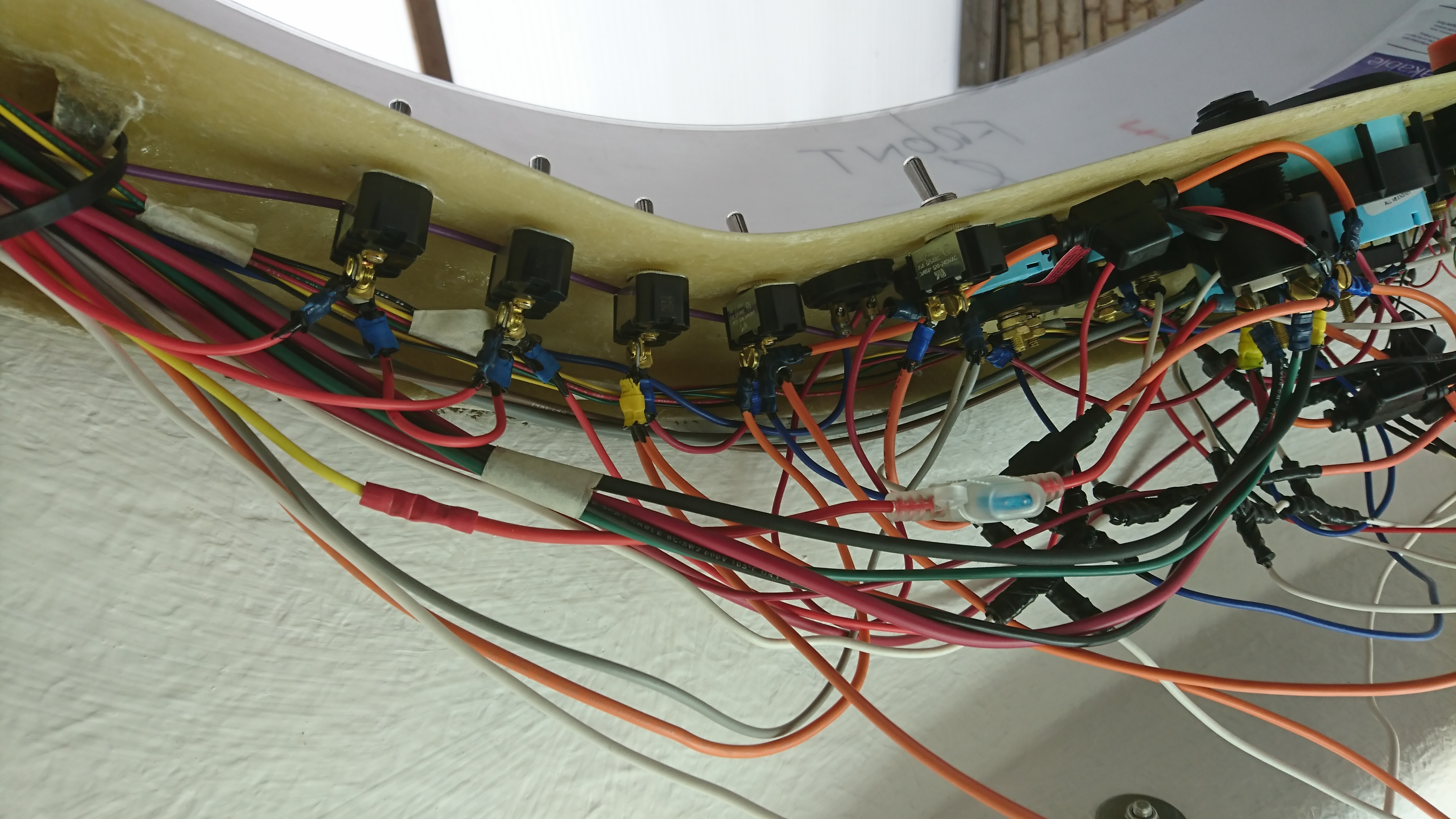
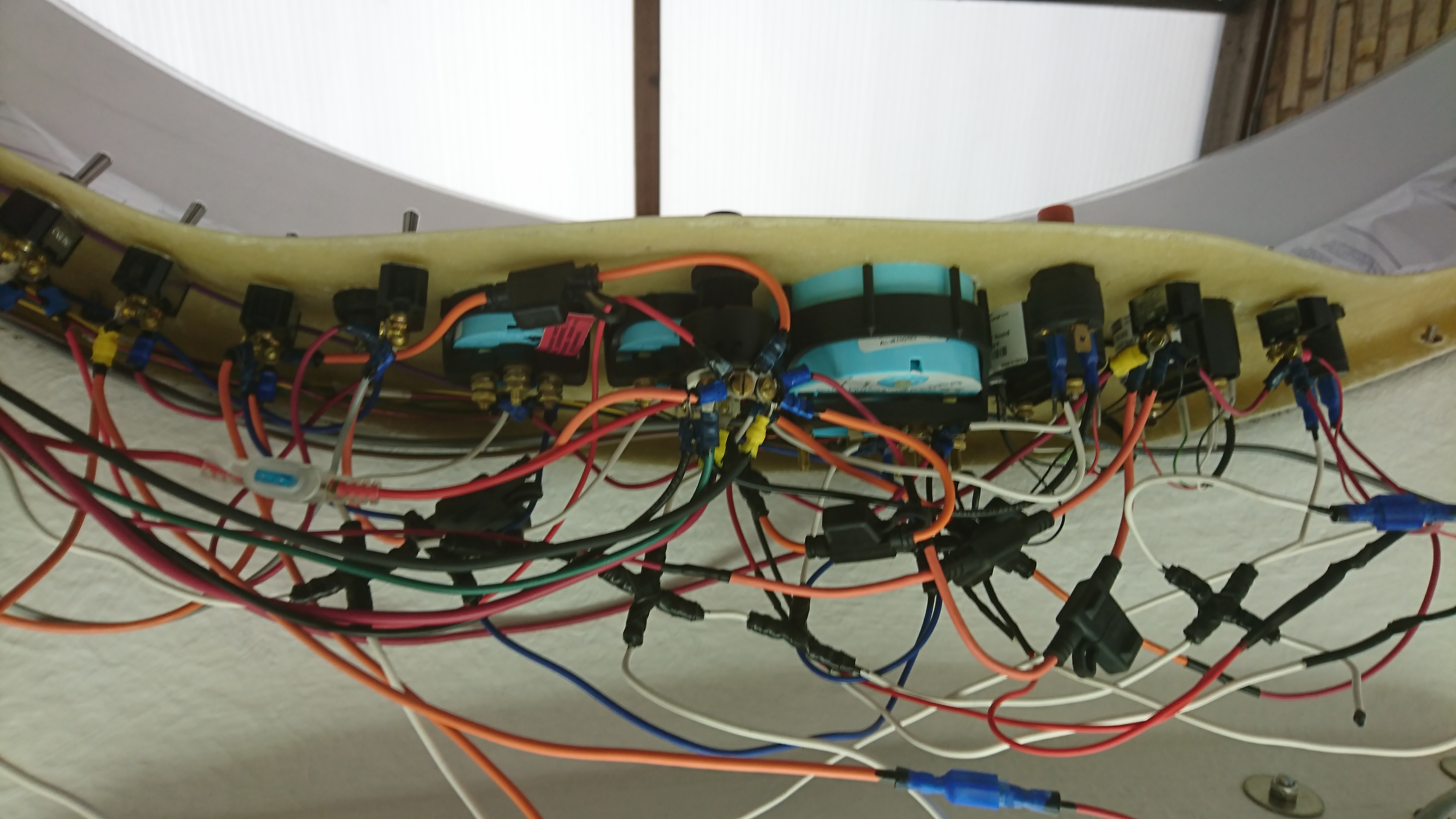
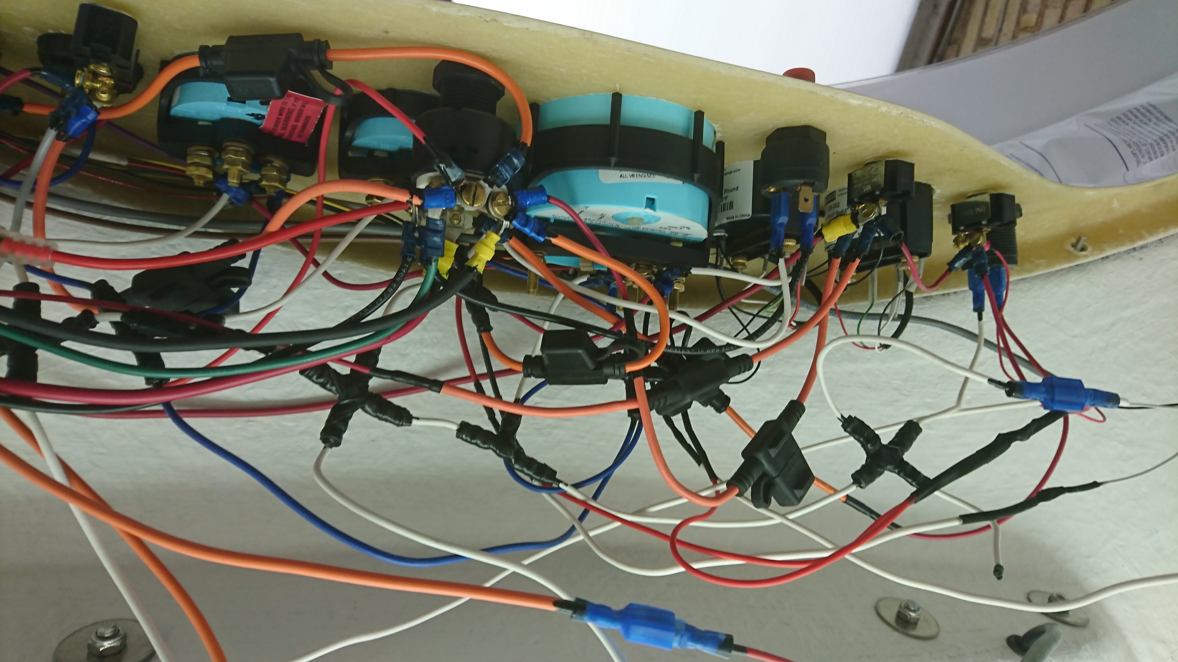
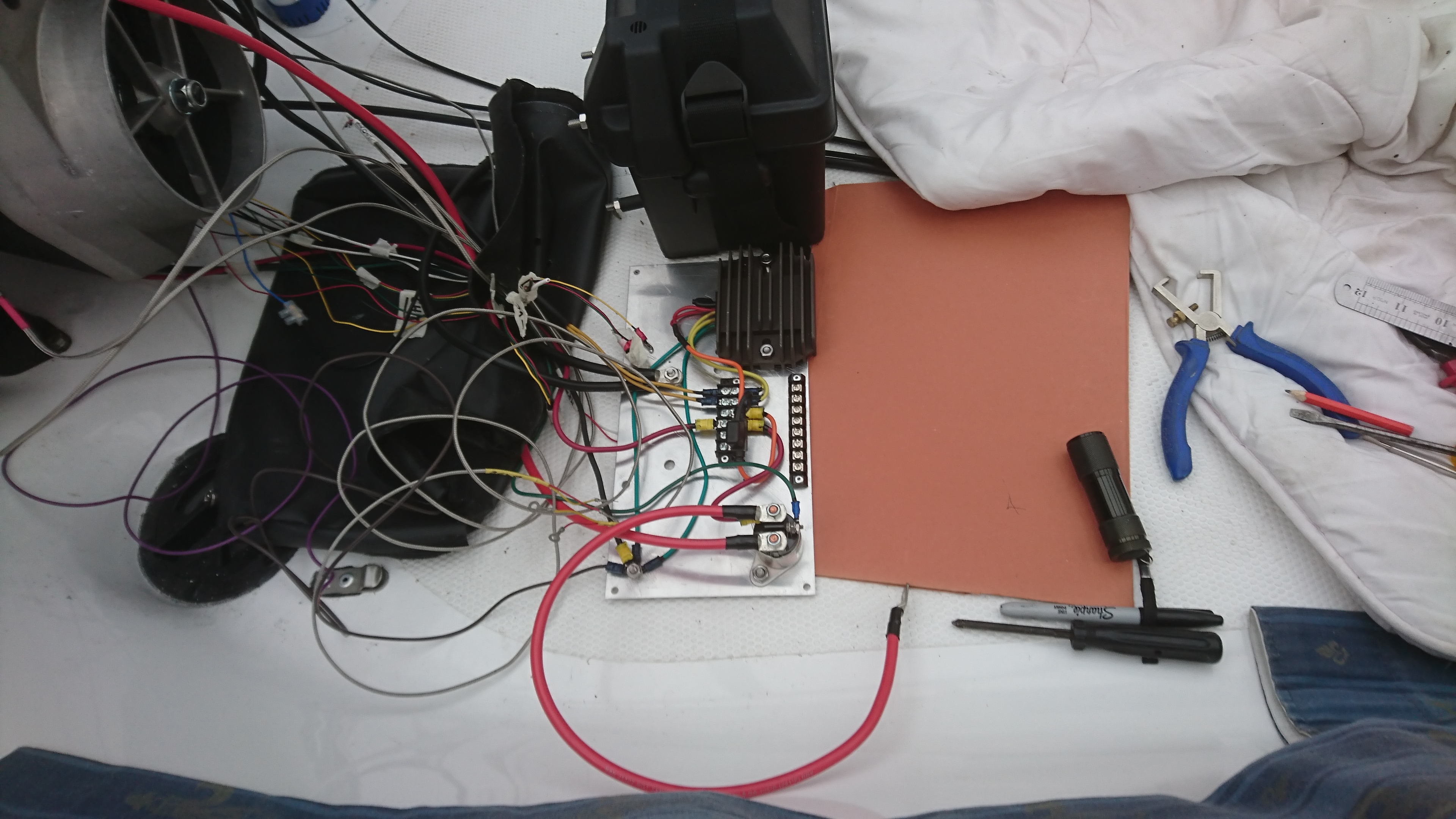
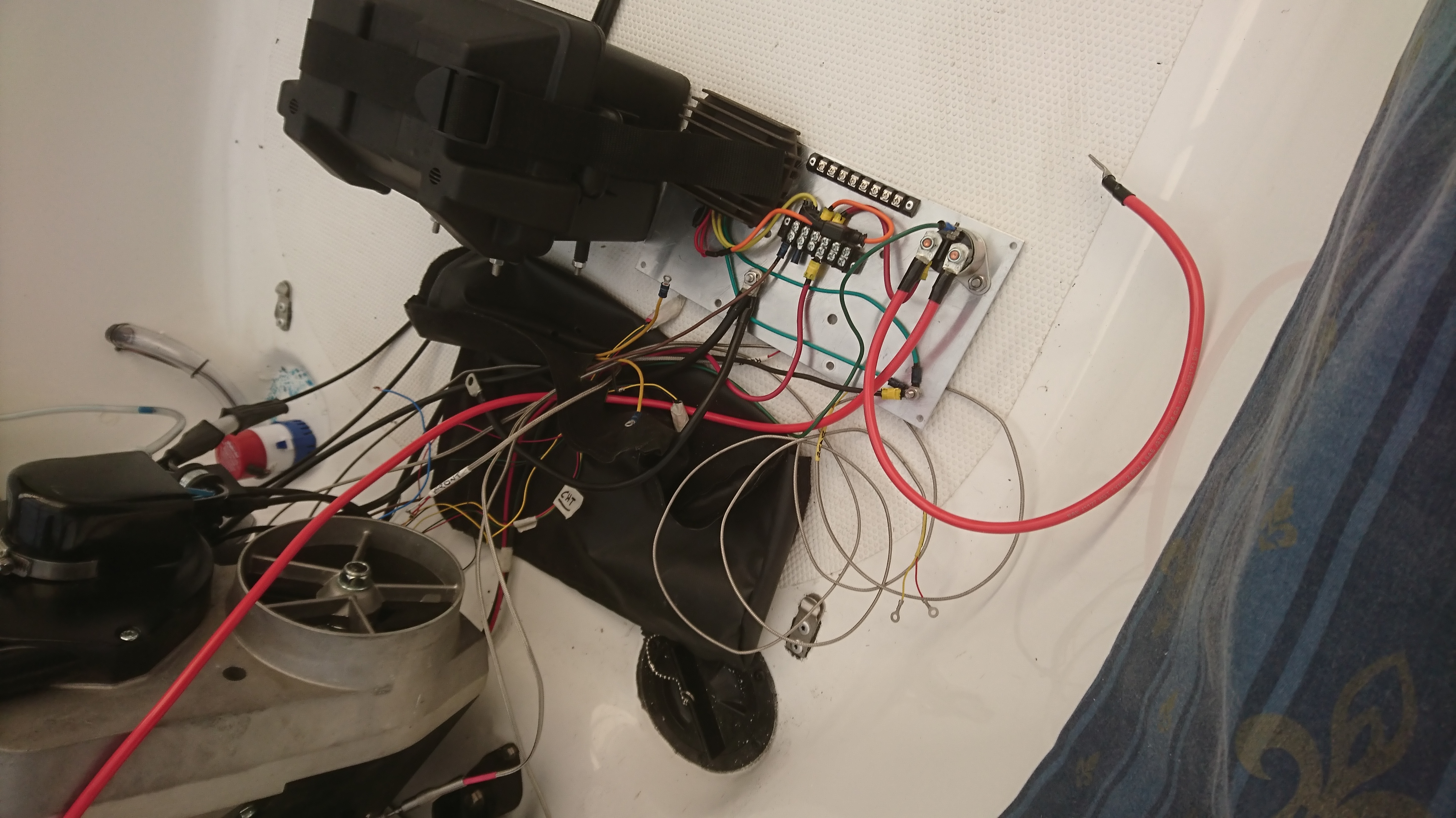
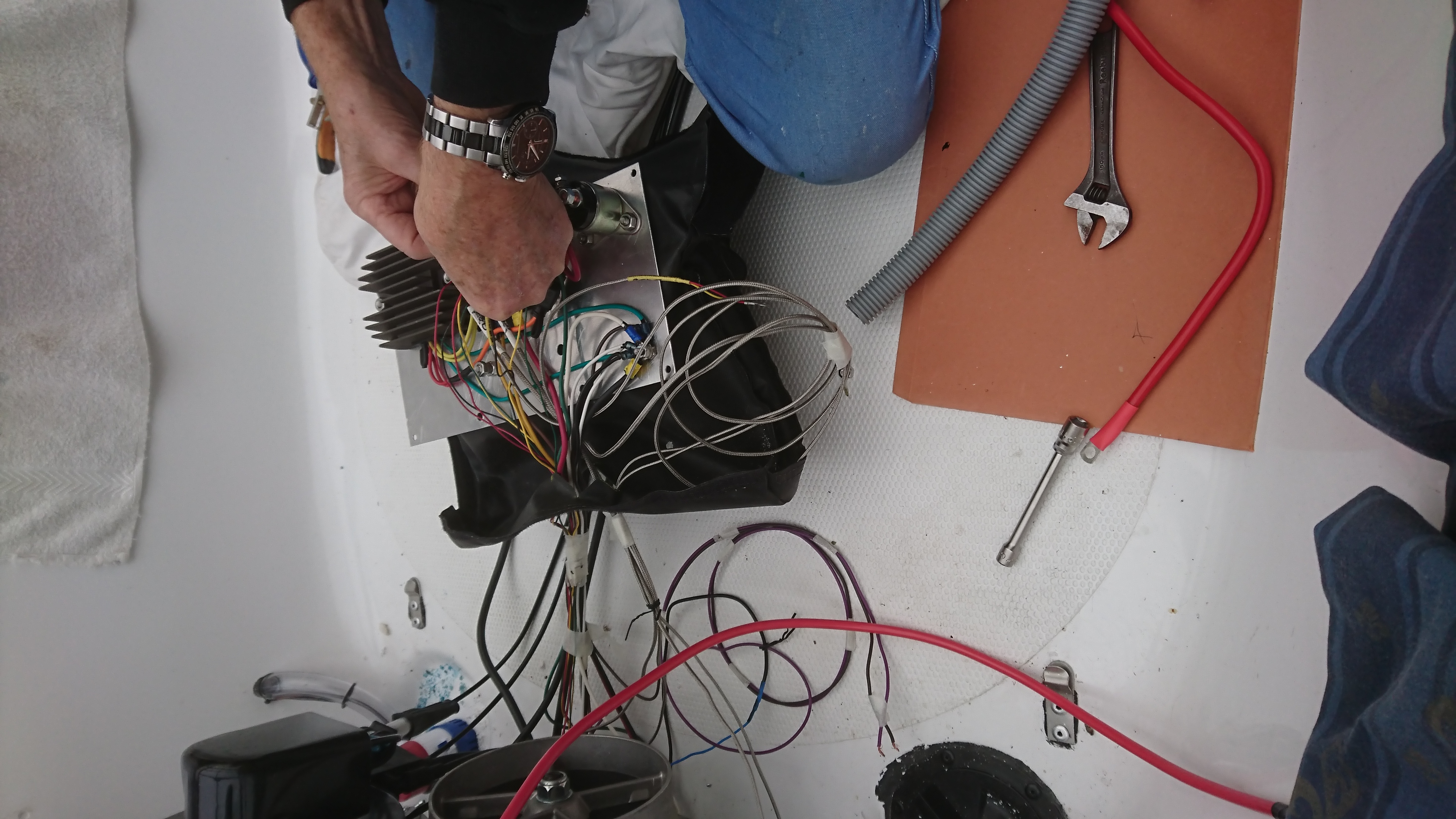
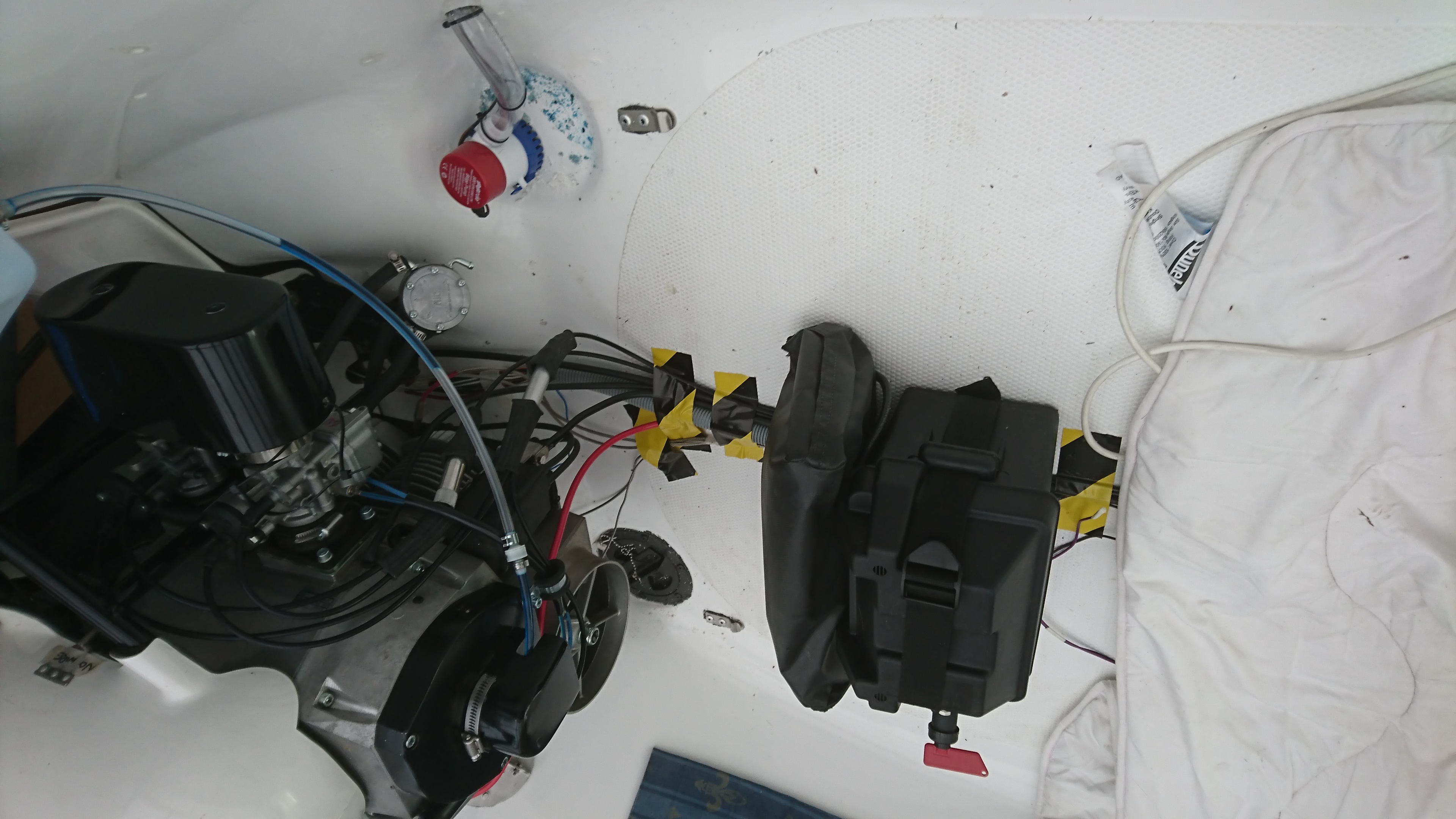
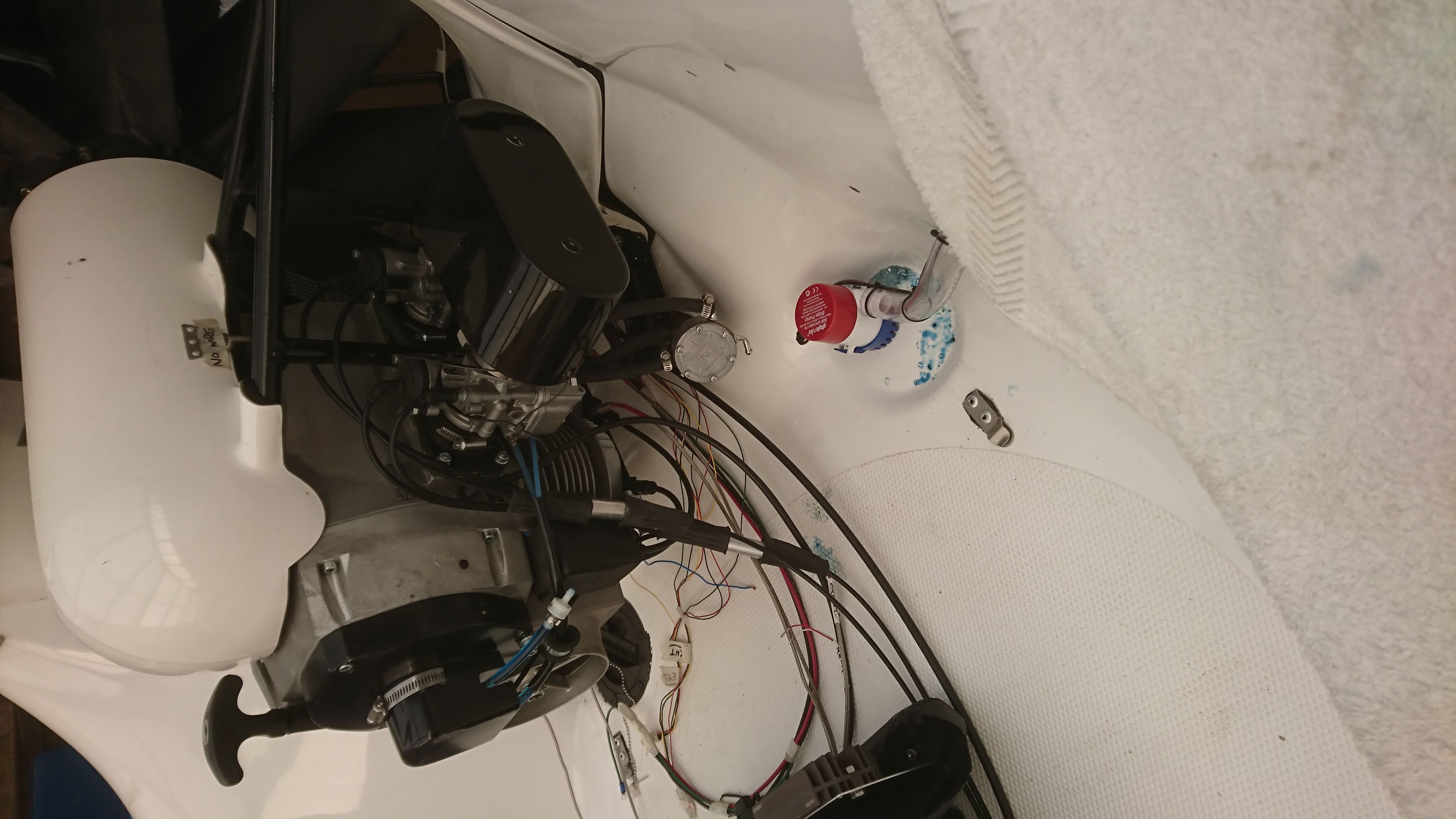
I did not think it necessary to show photos of the wiring diagrams enlarged and coloured as this is very basic, but very very helpful. I started with the Bilge Pump and progressed from there adding one item at a time. I was not under factory limitations, I could take my time and this I did. Every joint was sealed with a liquid rubber compound (see photo no. 24) and heat-shrink tubing. All the wires running down the port side duct were gathered together and tie-wrapped. The auxillary electrical plate was quite a challenge and great care was needed. I fitted a battery isolating switch in the battery box lid.
The reverse bucket computer control box was fitted as standard, see photo no. 3. Particular attention was given to the starboard bucket control cable as this passes over the exhaust pipe. It was double tie-wrapped with heaving duty ties – see photo no. 4.
Bucket computer control box fitted
Starboard Bucket control cable double strapped above exhaust
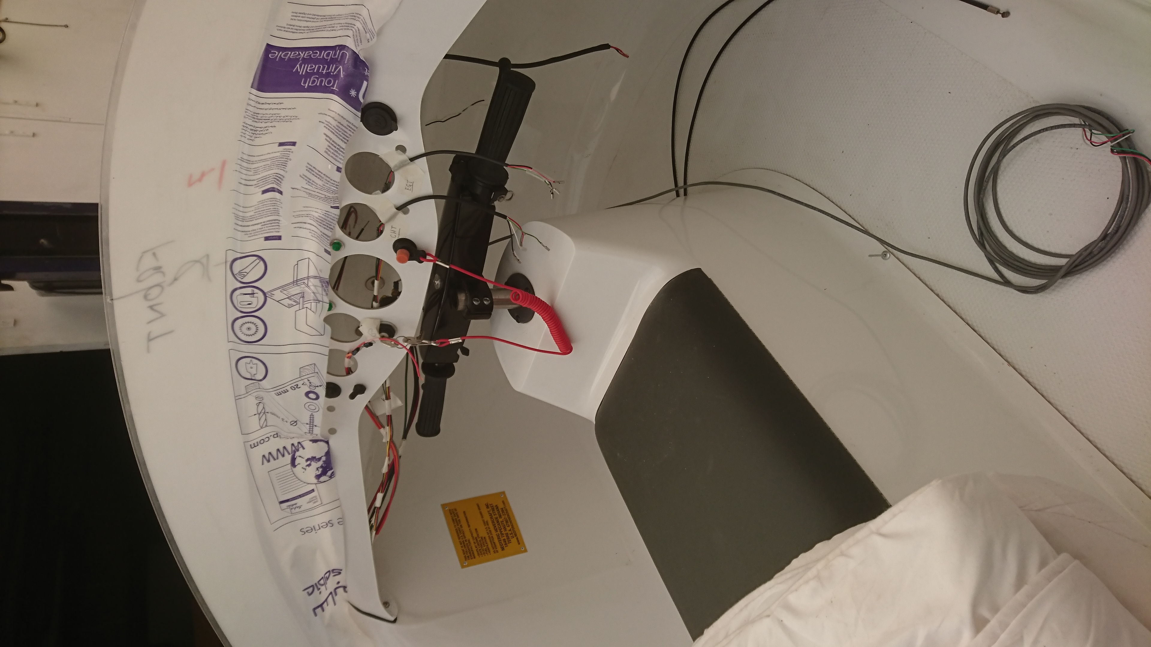
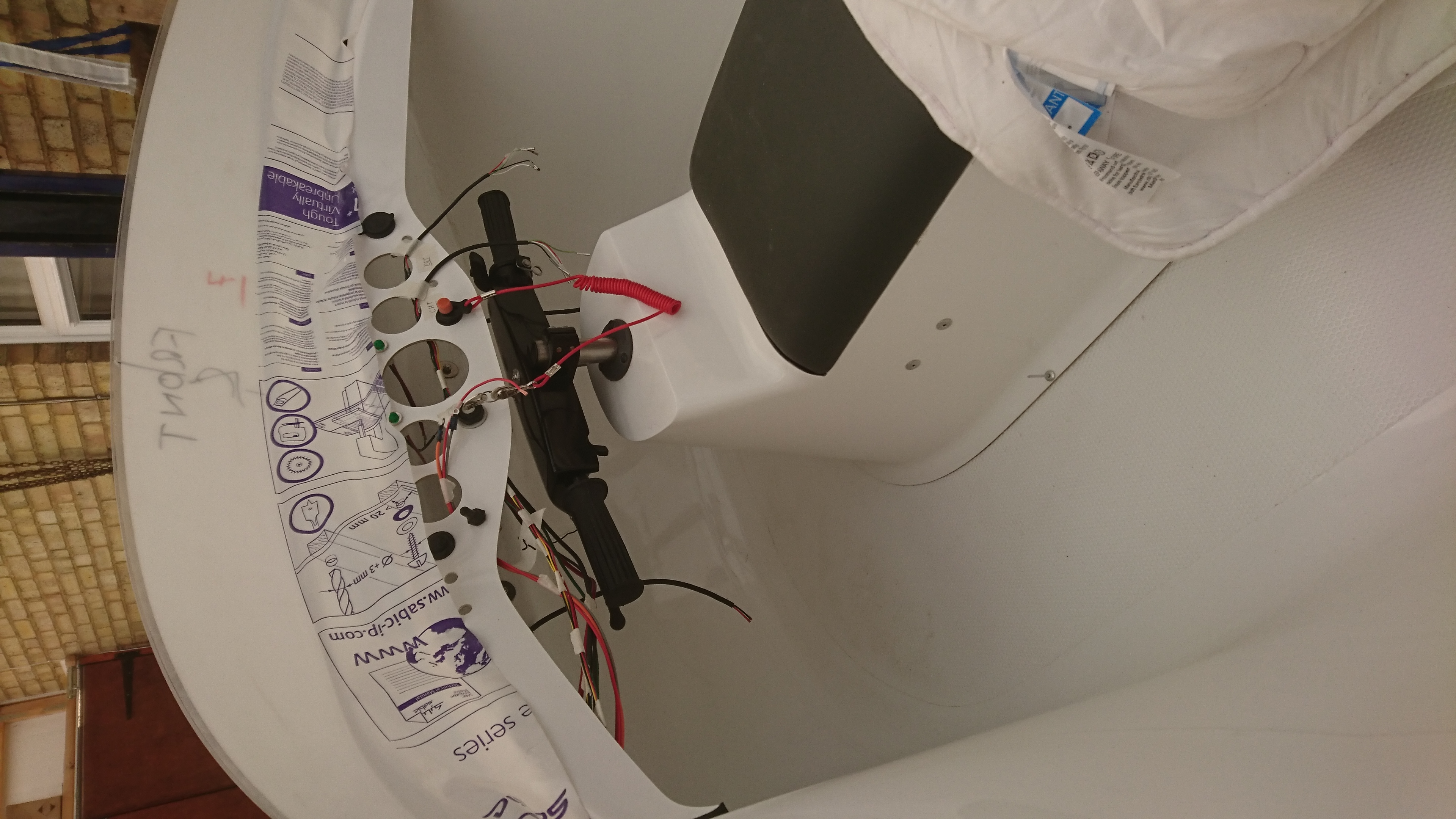
Wiring started to be threaded into instrument panel
Another view of wiring being threaded into panel
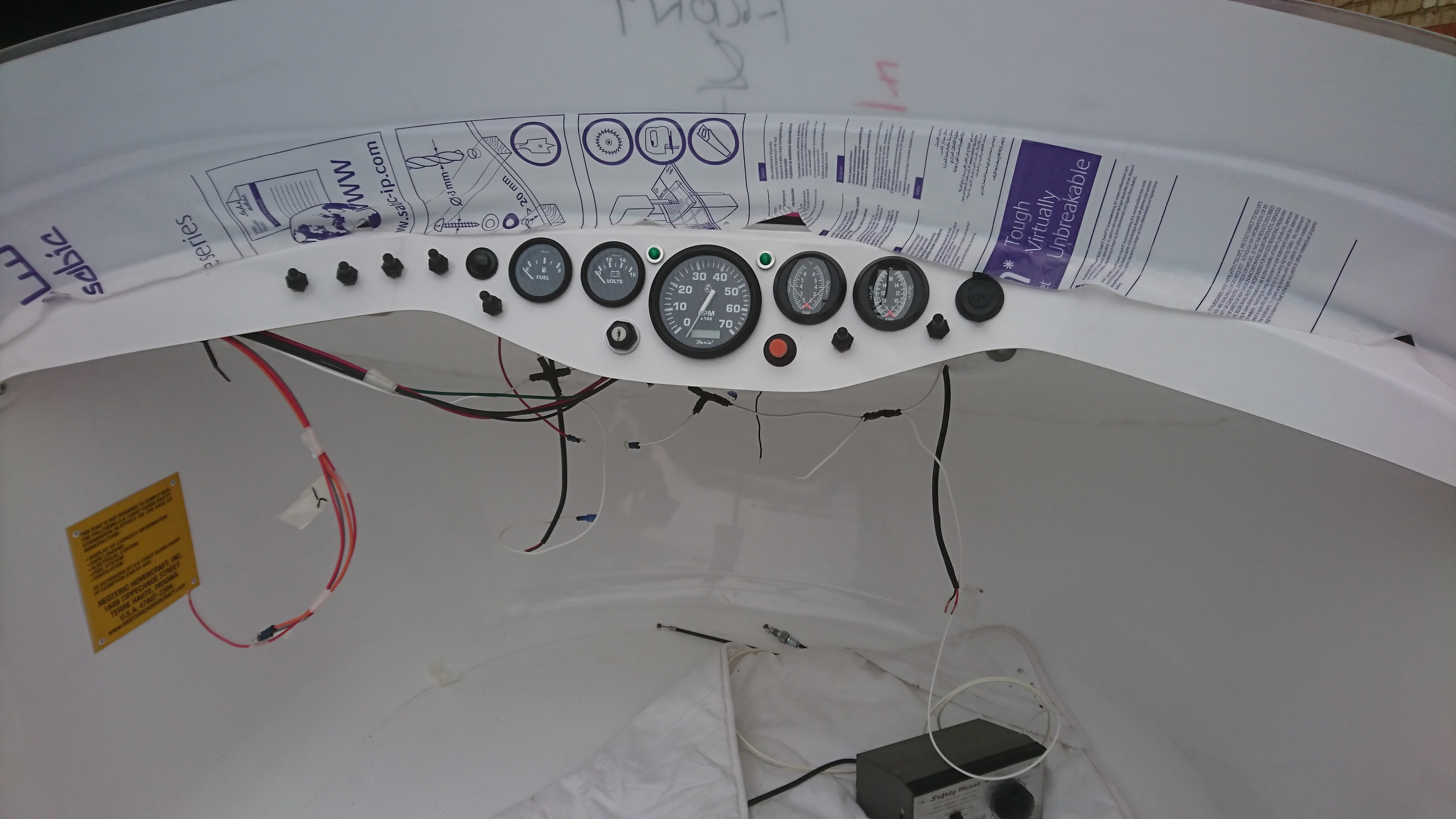
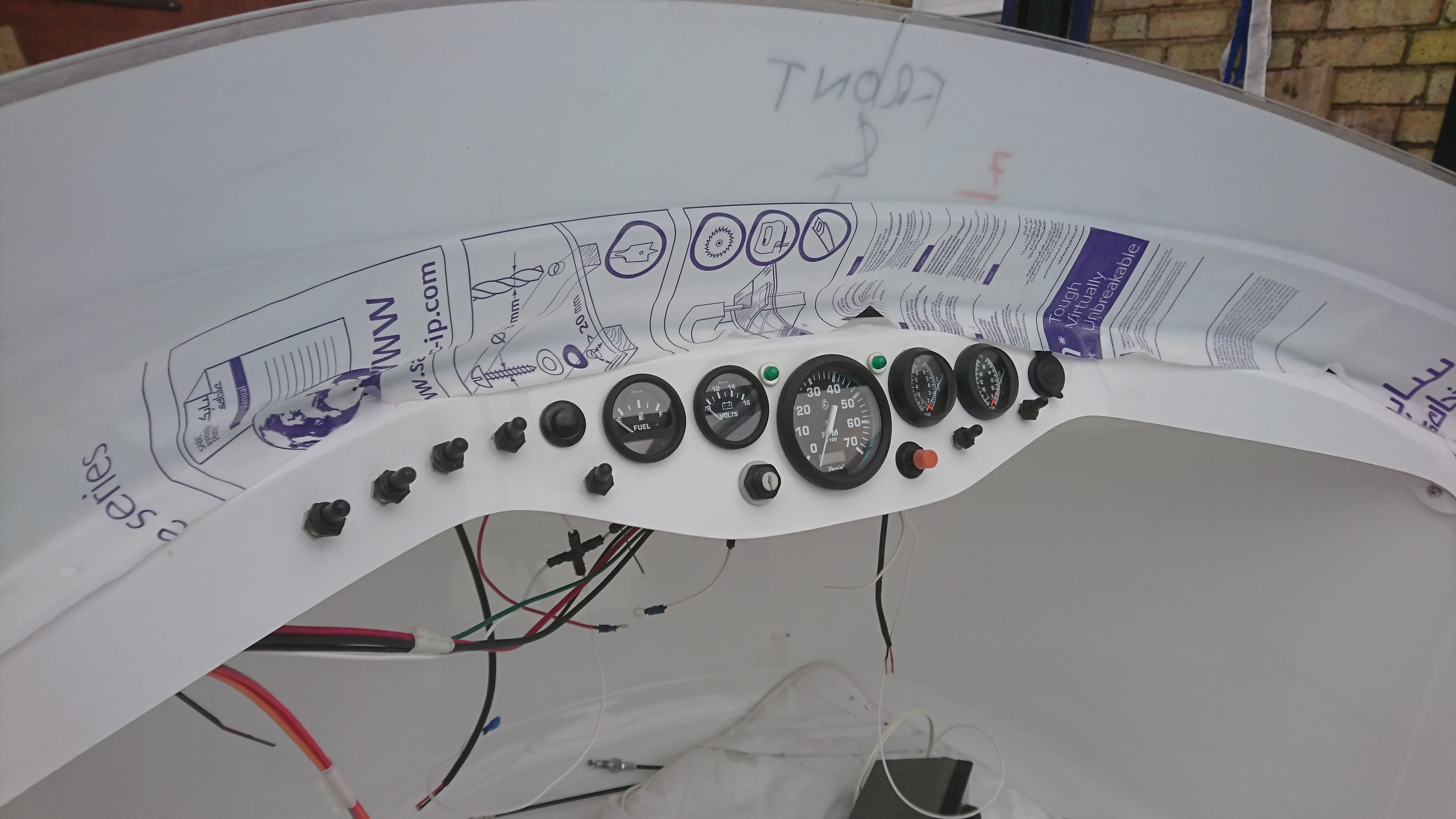
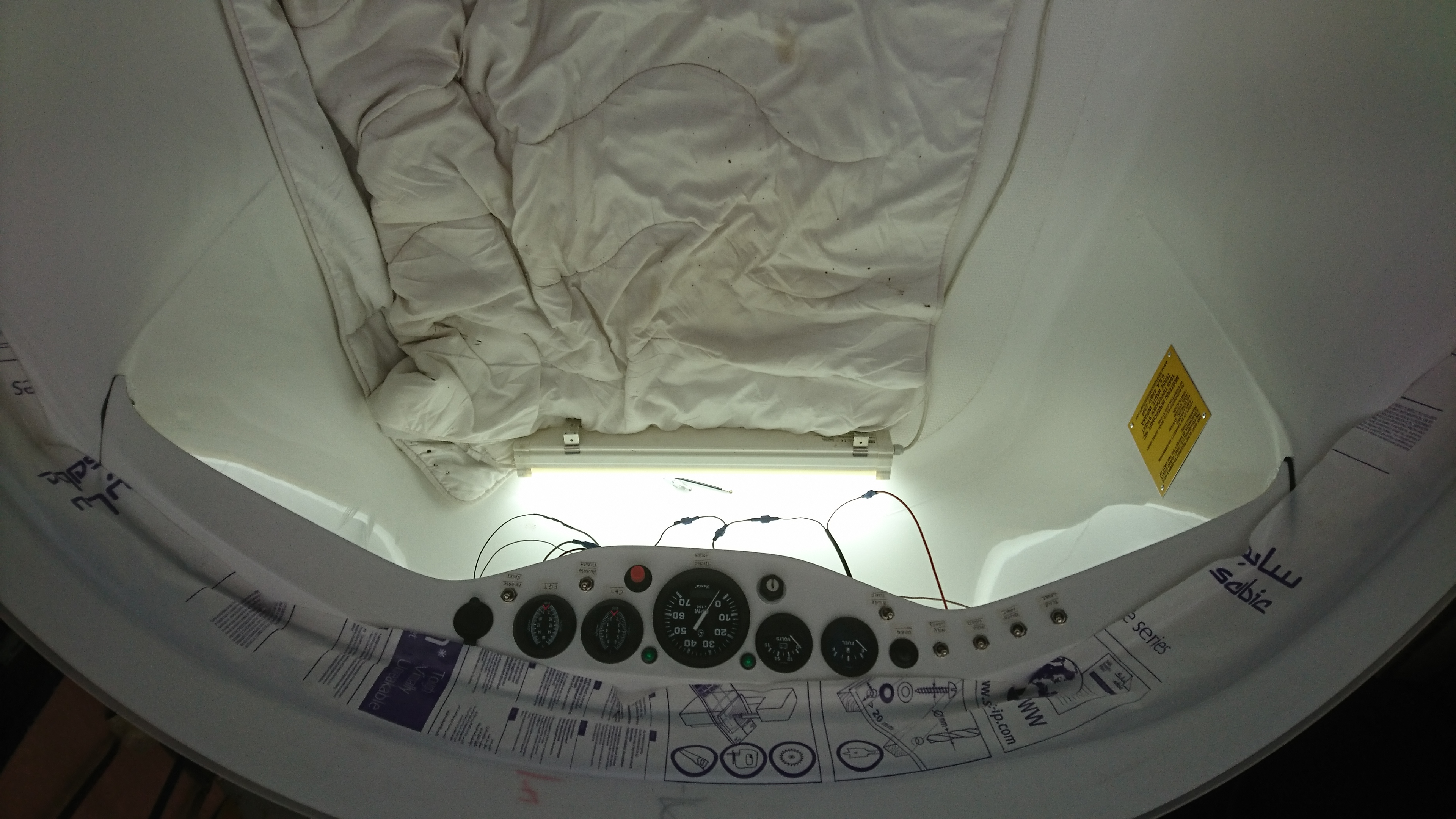
Instruments and switches fitted
Another view of instrument and switch panel
Best way we found to complete wiring,on your back
Under-dash Starboard side
Starting to wire up Auxillary Electrical Plate
Continue wiring up electrical plate
More wiring of the Auxillary Electrical Plate
Starting to tidy up. Battery box now secured
Checking electrical plate to battery box fitment
Note Battery Isolating Switch fitted into battery box lid
Overview of all connections to power unit
Some of the wiring diagrams enlarged and coloured in
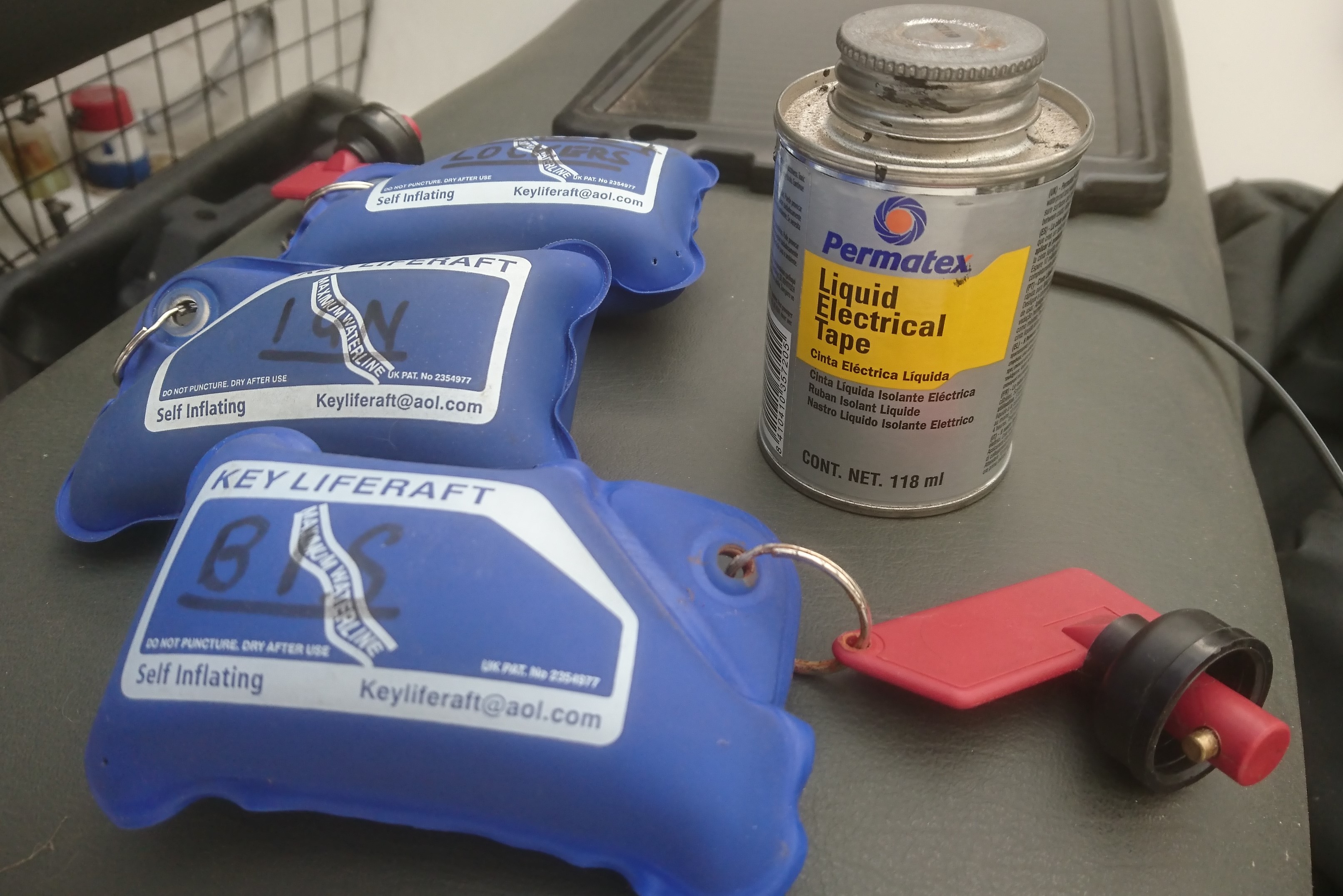
All keys kept on a 'Key Liferaft' and the Permatex Liquid Electrical Tape code 35720 118ml. I applied it with a cocktail stick. Fiddly and time consuming but well worth it. Easily available in the States
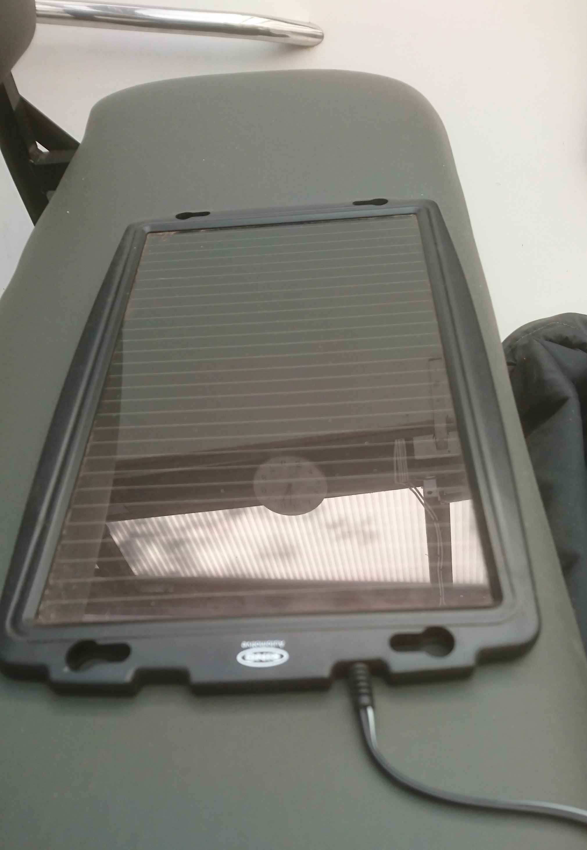
12 Volt Solar panel for keeping the Battery fully charged. Ring RSP240 12v up to138 mA ,suitable for Battery up to 100Ah
14. Guard Clips and Glove Boxes
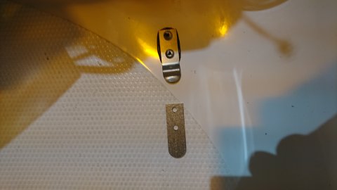
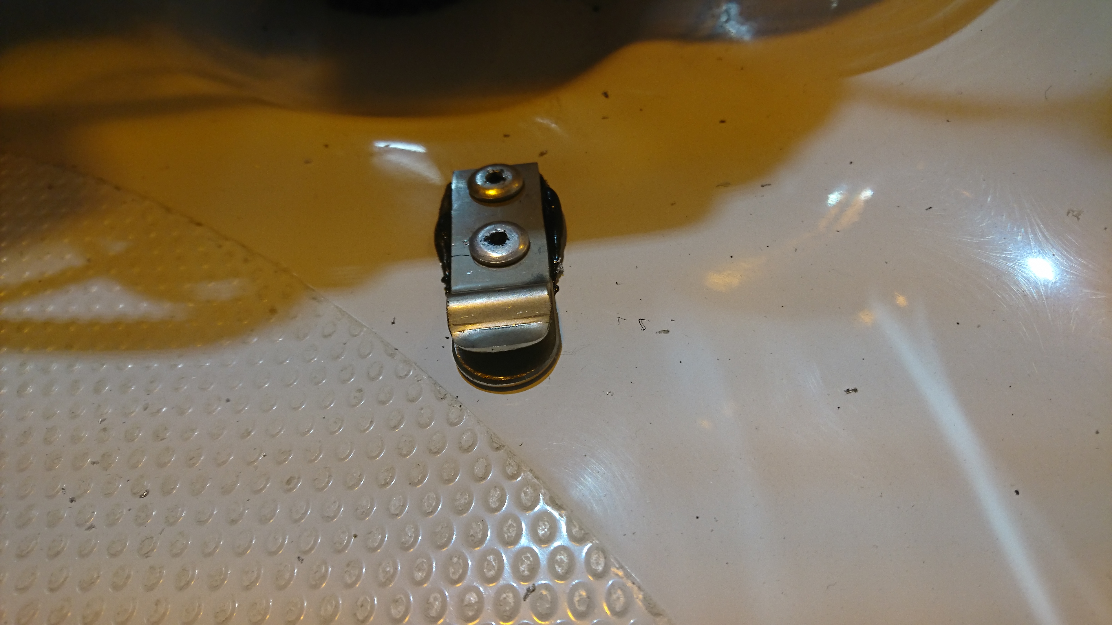
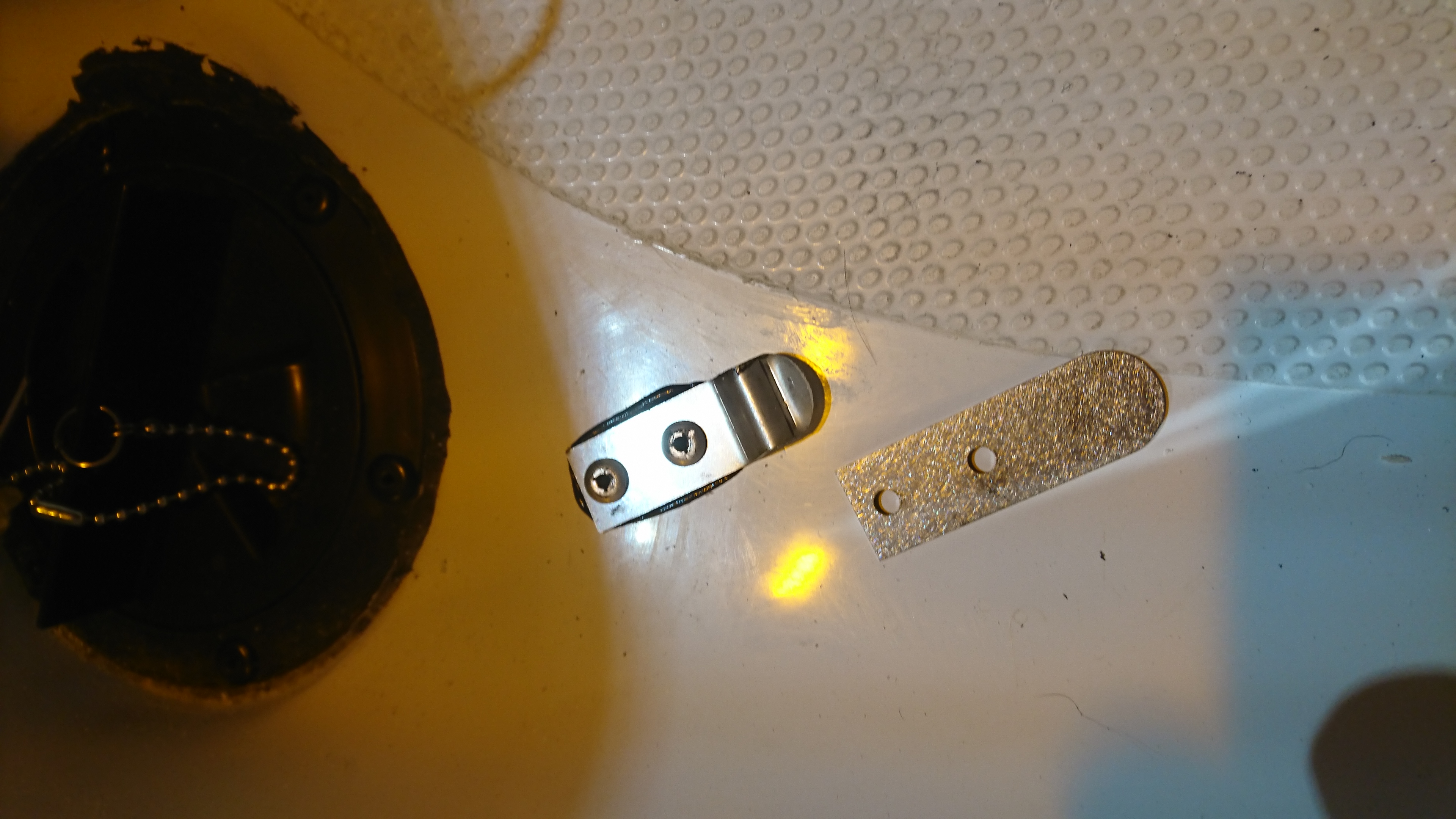
One of the modifications was the fitting of extra lower supports to the guard clips. This was not mentioned and it was not until I found these support pieces as spare that I realised what they were for. The photos nos. 1 and 3 show these. For fitting the glove boxes, mark out as per the instructions. Best leave them a snug fit and sealed in.
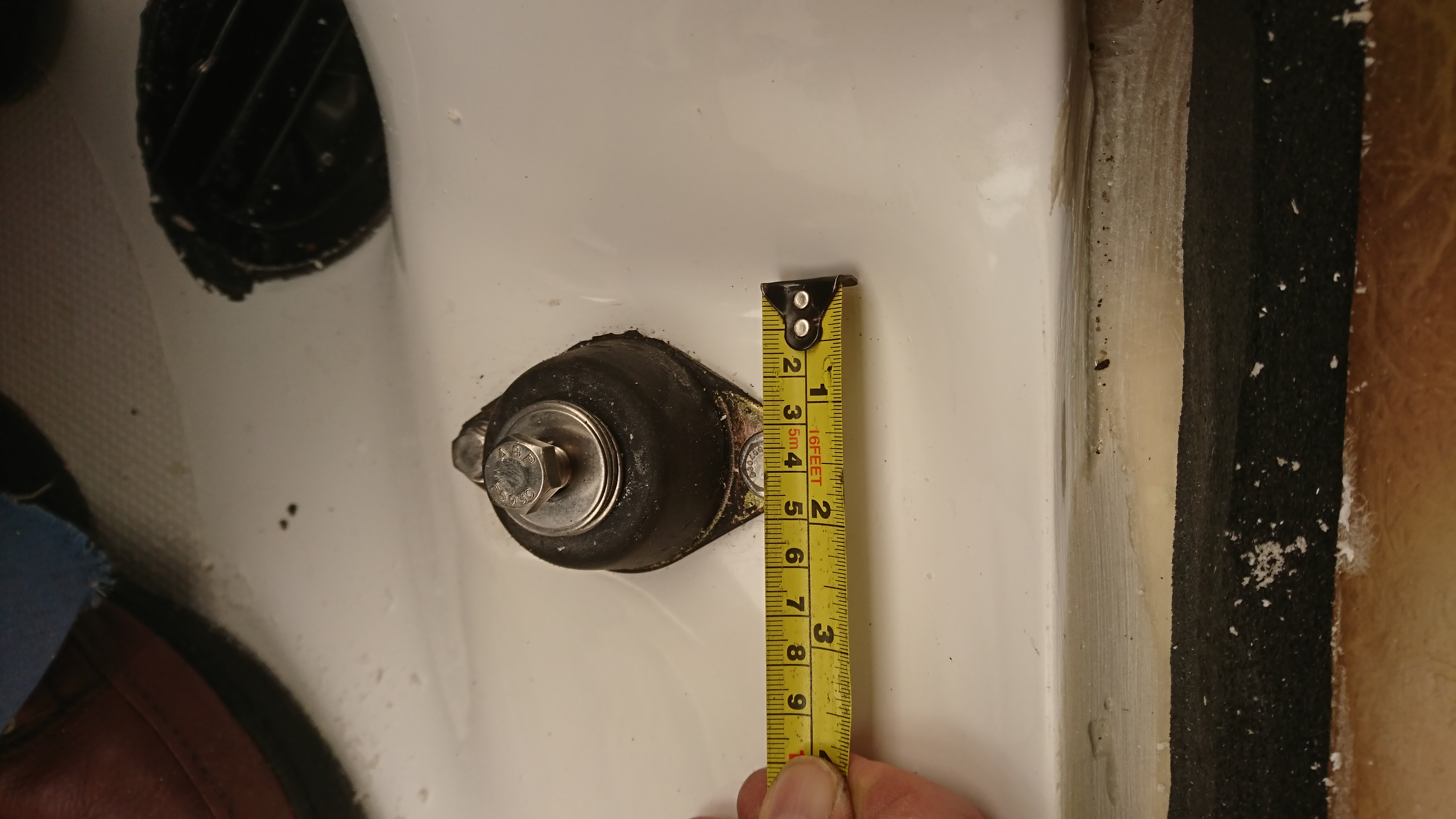
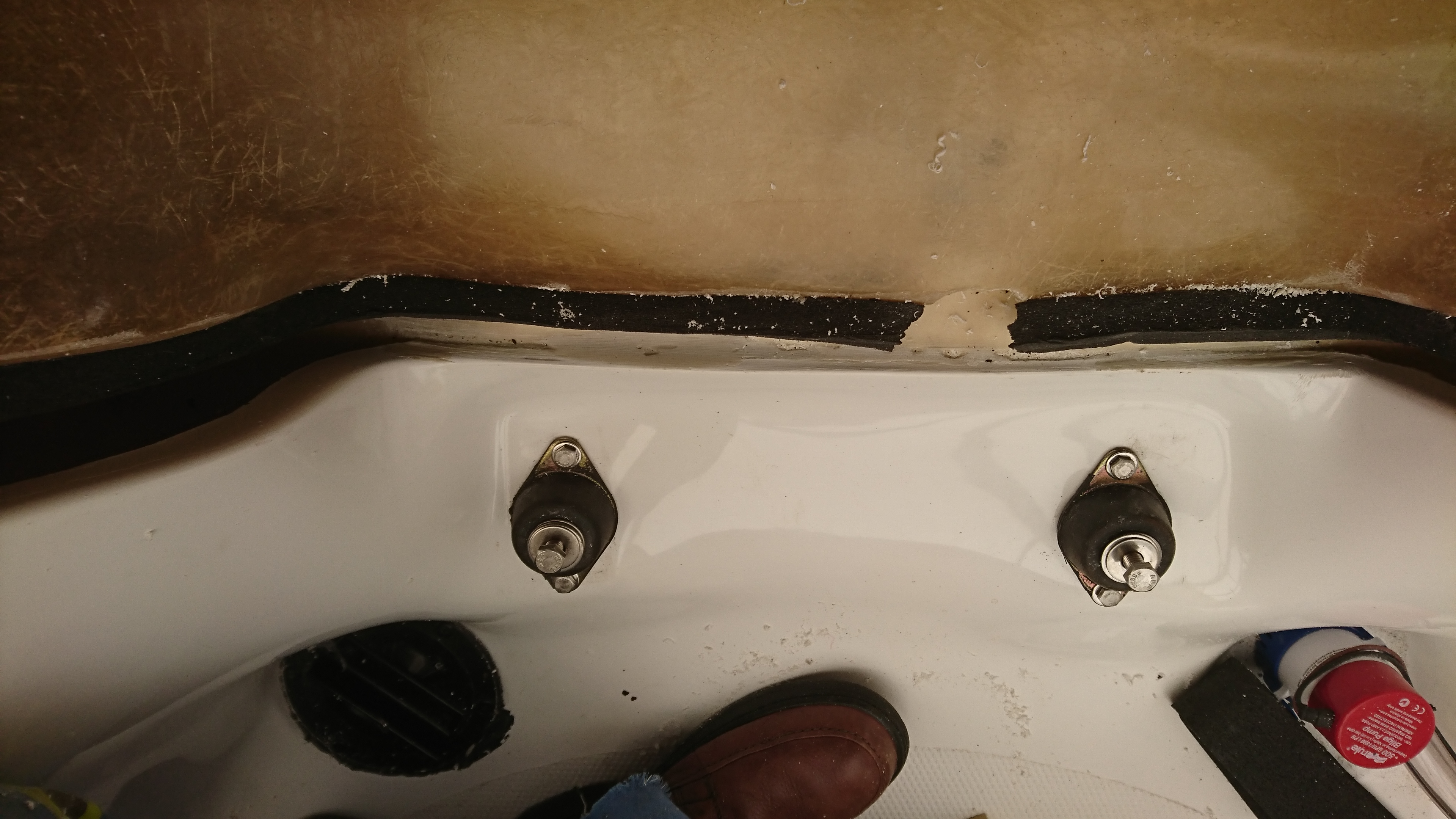
Guard clip Port side plus extra lower support
Guard clip Port side completed
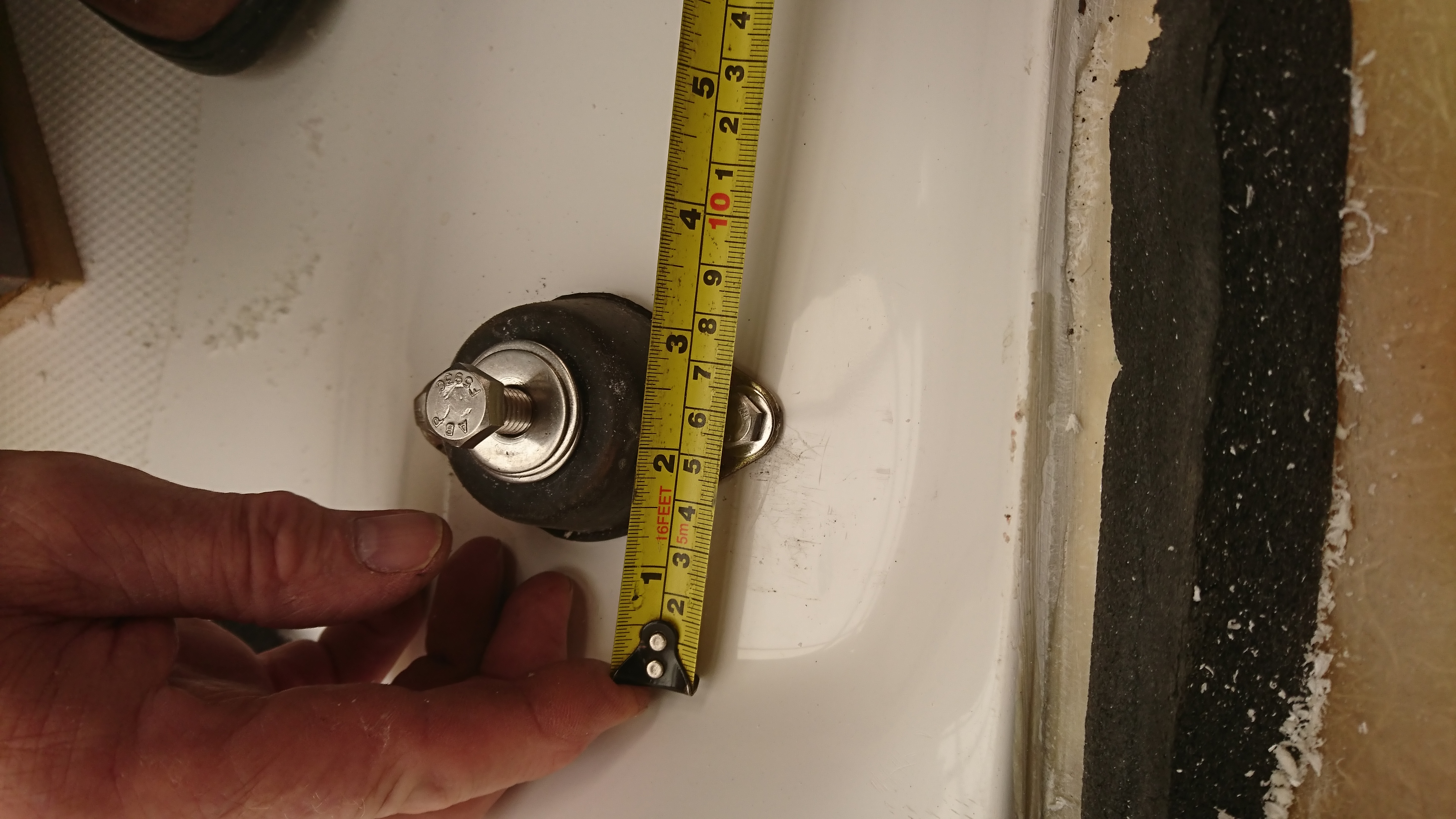
Guard clip Starboard side plus extra lower support
Starboard Guard Clip completed
Starboard side Standard Glove Box
Port side Standard Glove Box
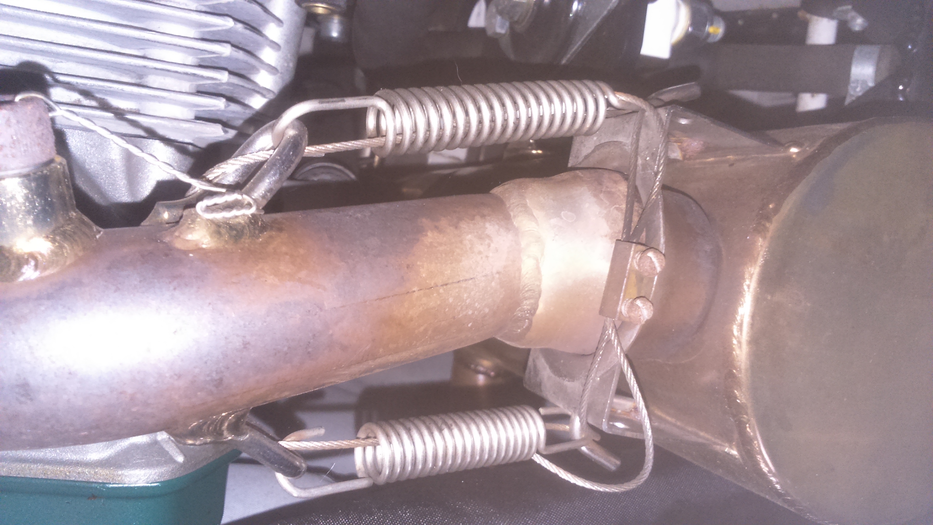
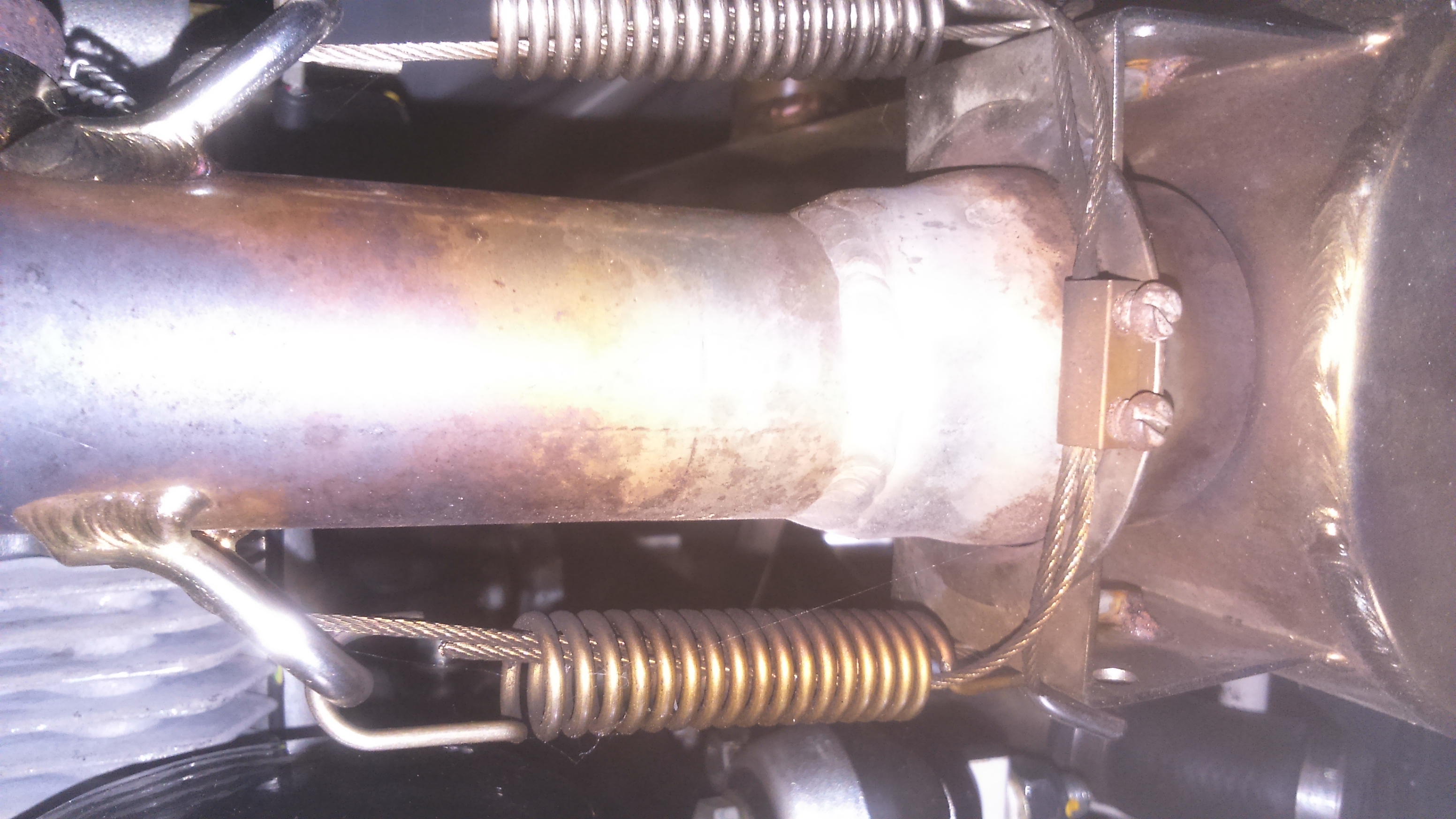
15. Exhaust
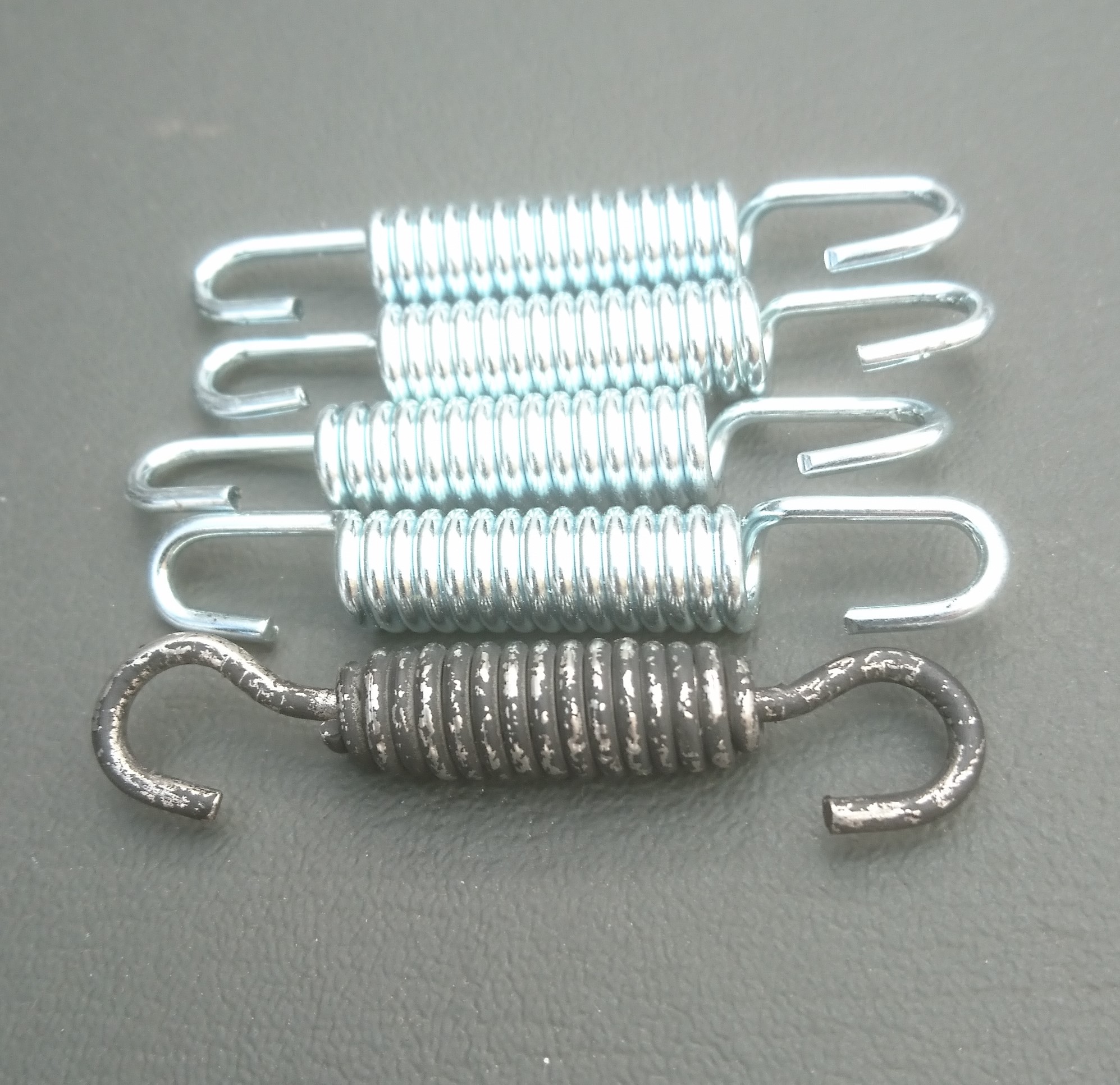
I found the original springs difficult to pass the security wire through. When visiting Little Gransden Air Show, I wandered into a hangar with microlight aircrafts in. Looking at the exhaust on a McCulloch power unit I saw something I liked the look of photos nos. 2 and 3. Enquiries led to the internet and I sourced these stainless steel springs from France. I got four sets of four – all different lengths. They were very inexpensive. Photo no. 5 shows the result and I am very pleased with it.
Hovertrek exhaust with original springs
Micro-light exhaust at Little Gransdon
Micro-light exhaust a better view
Modified Hovertrek exhaust spring system
Hovertrek exhaust with new type springs and security wire in place
4 New spare exhaust springs,original in the foreground
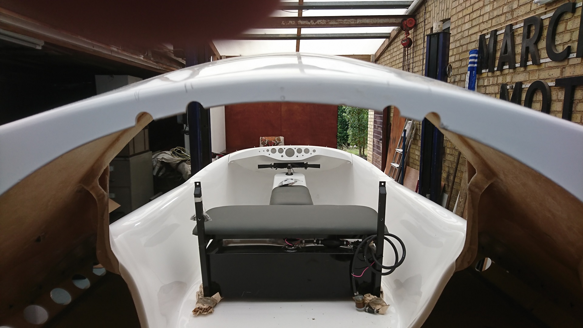
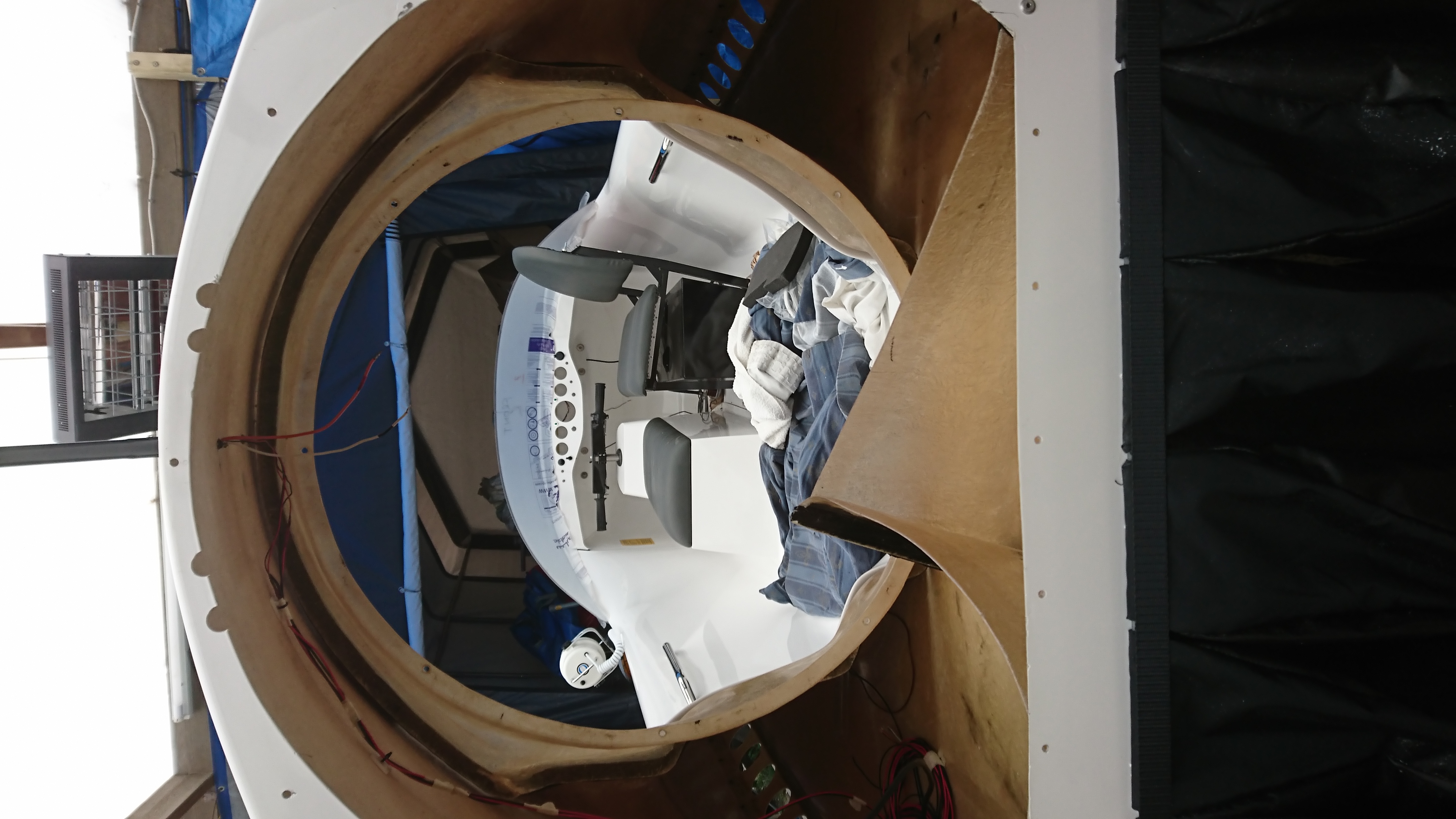
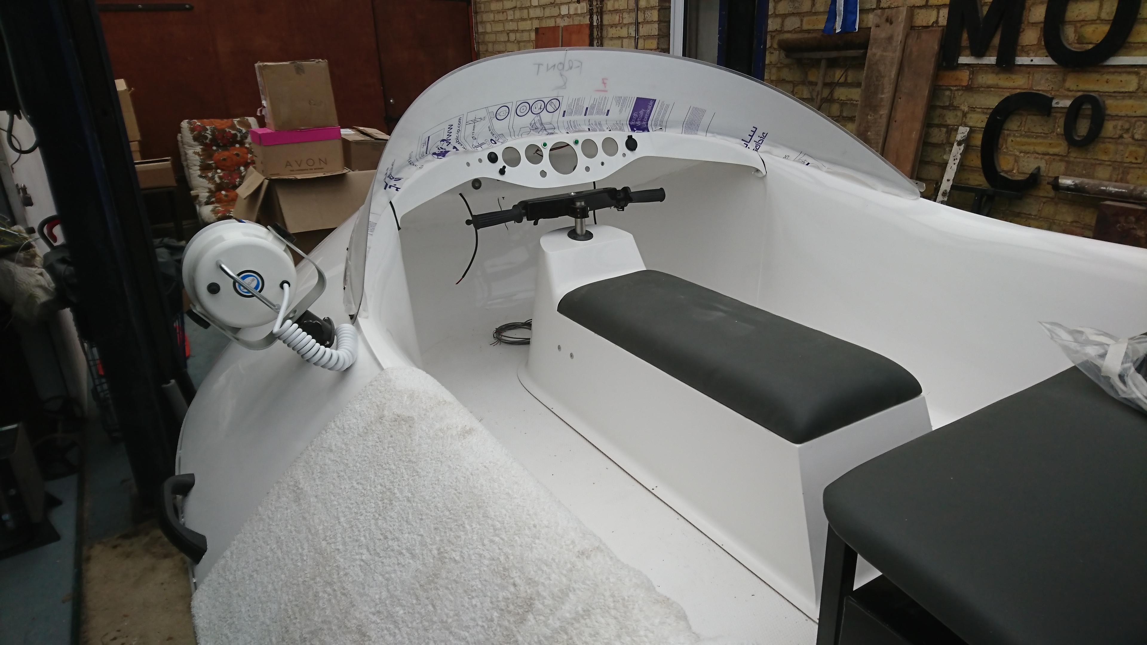
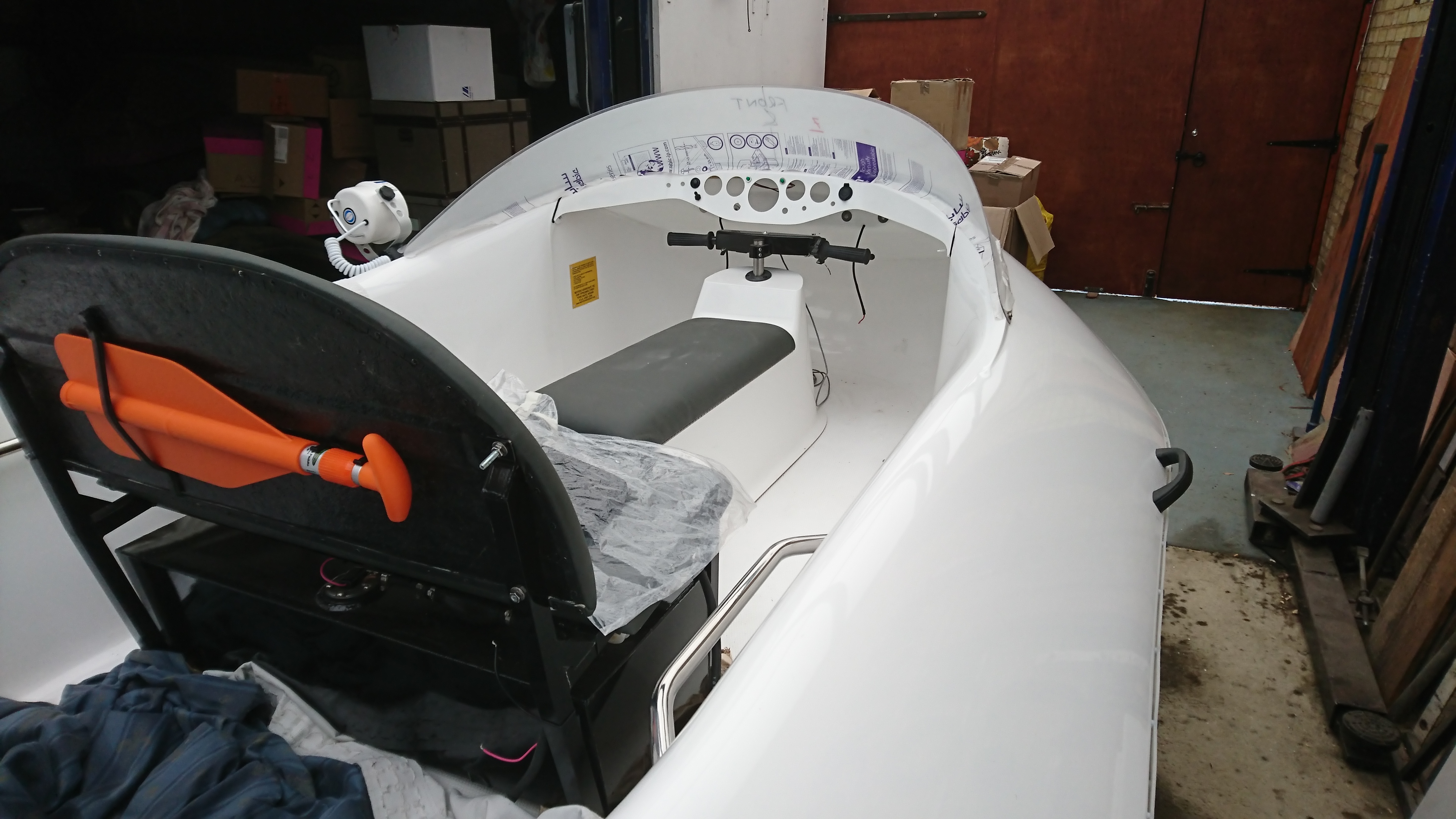
16. Instrument Panel and Seating
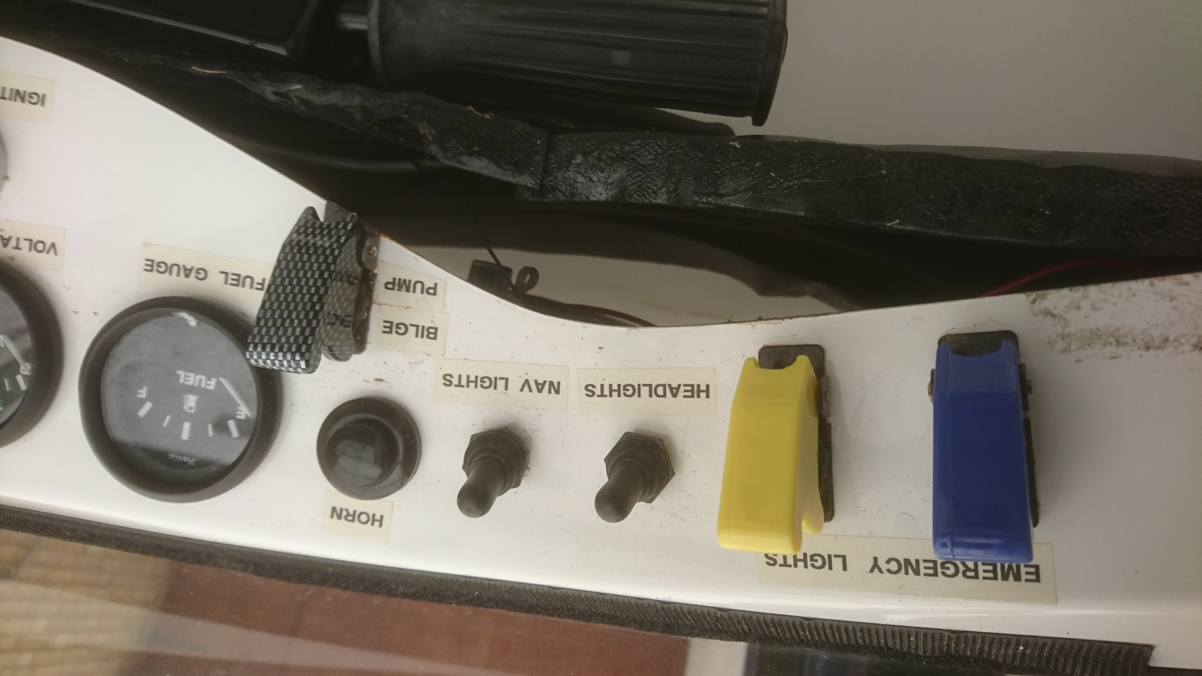
This craft was supplied with a detachable instrument panel already drilled-out, I only added a couple of extra holes for extra switches. Although maybe should be included in the wiring, the yellow light, blue light and bilge pump switches have aircraft type covers fitted to avoid accidental use.
US Coast Guard capacity label marked out with 3 Horn rivets behind label
Detachable instrument panel fitted
Checking position of seats before marking,drilling and bolting down
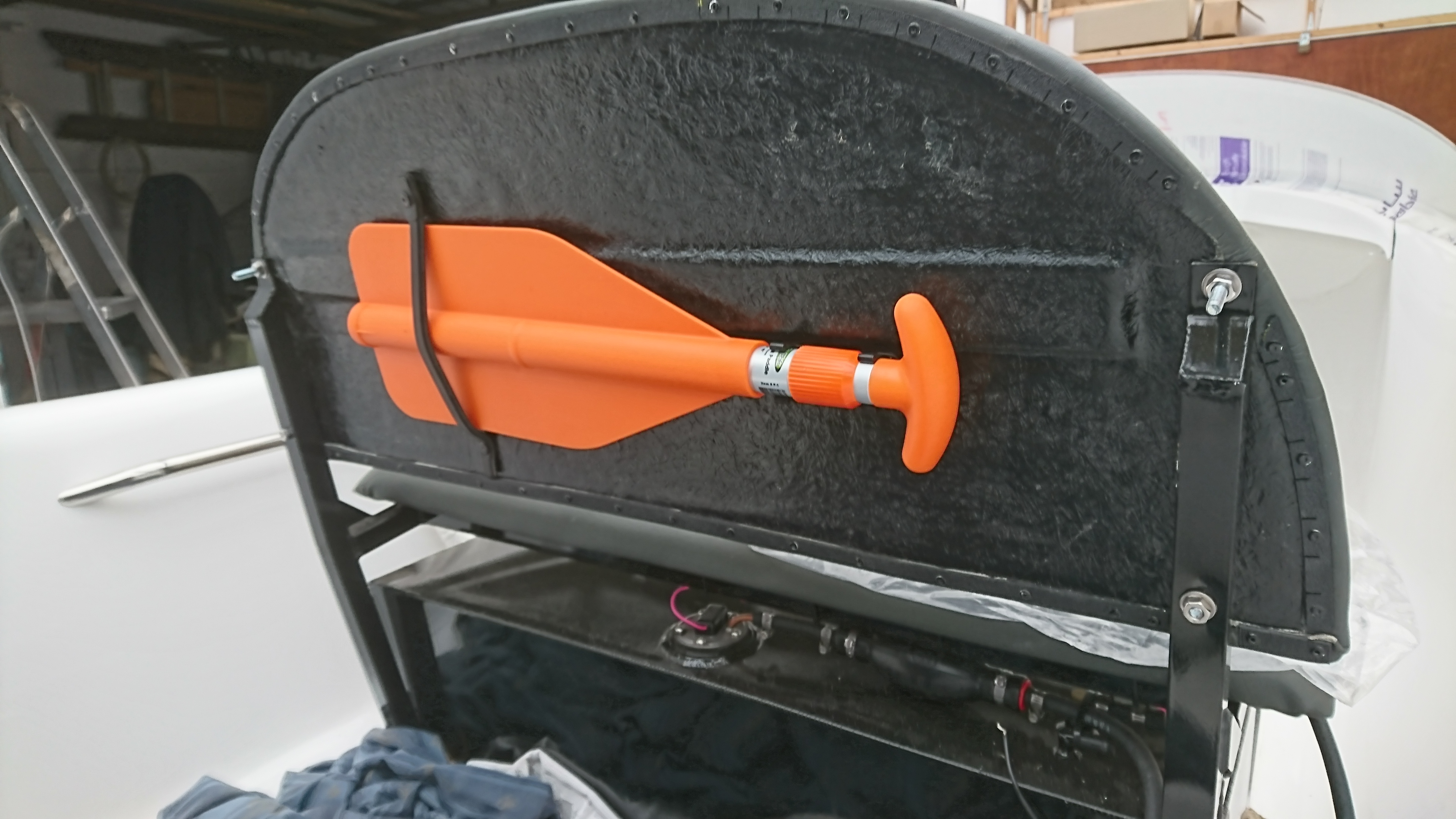
Rear seat with paddle and long range fuel tank
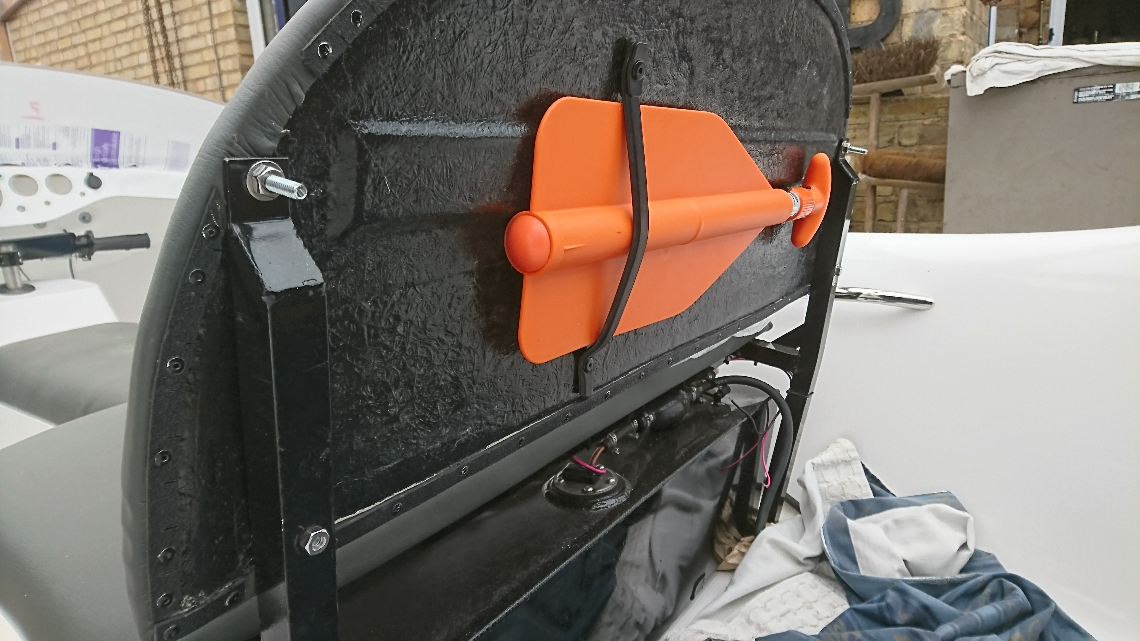
Another view of rear seat with paddle and long range fuel tank
Emergency Blue and Yellow Lights and Bilge pump all fitted with aircraft style safty covers. Prevents you switching on by accident
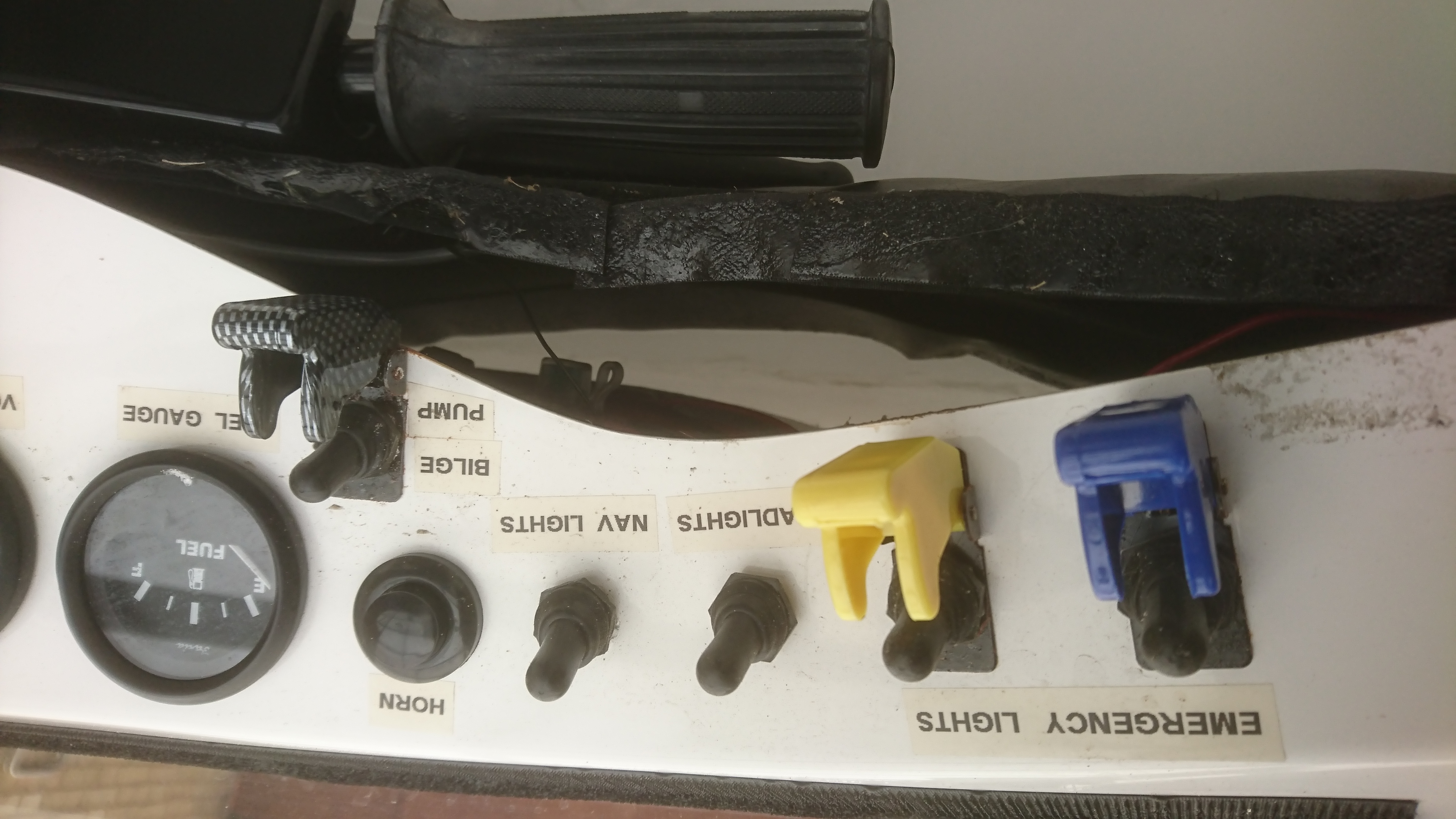
View as per photo 6 but with all covers open
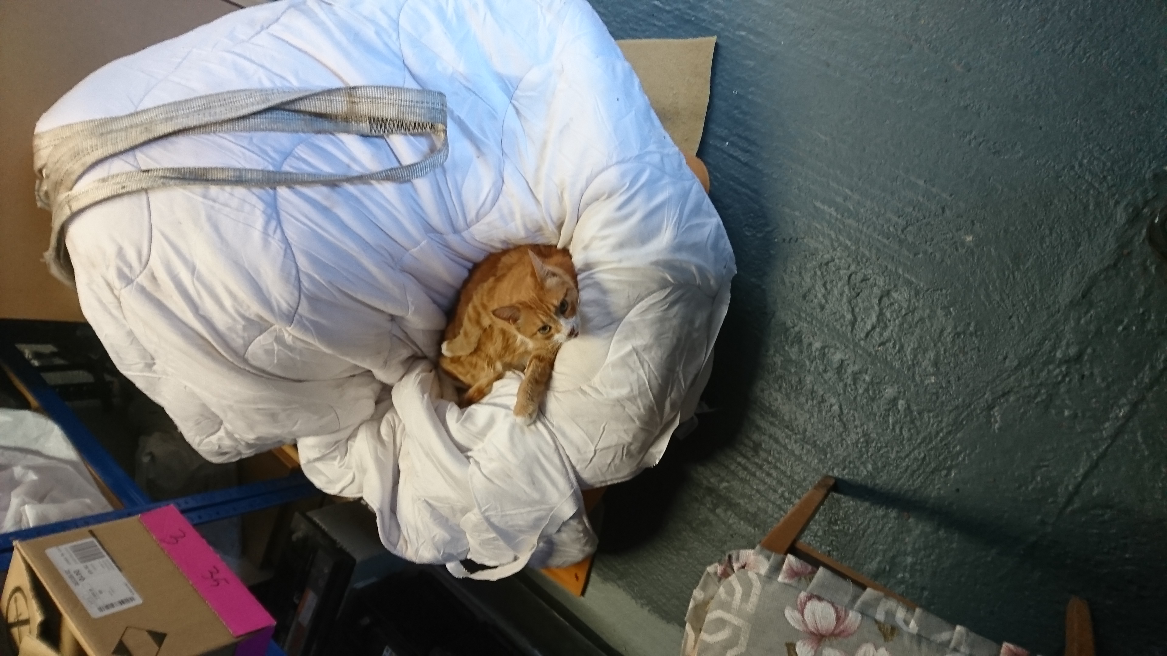
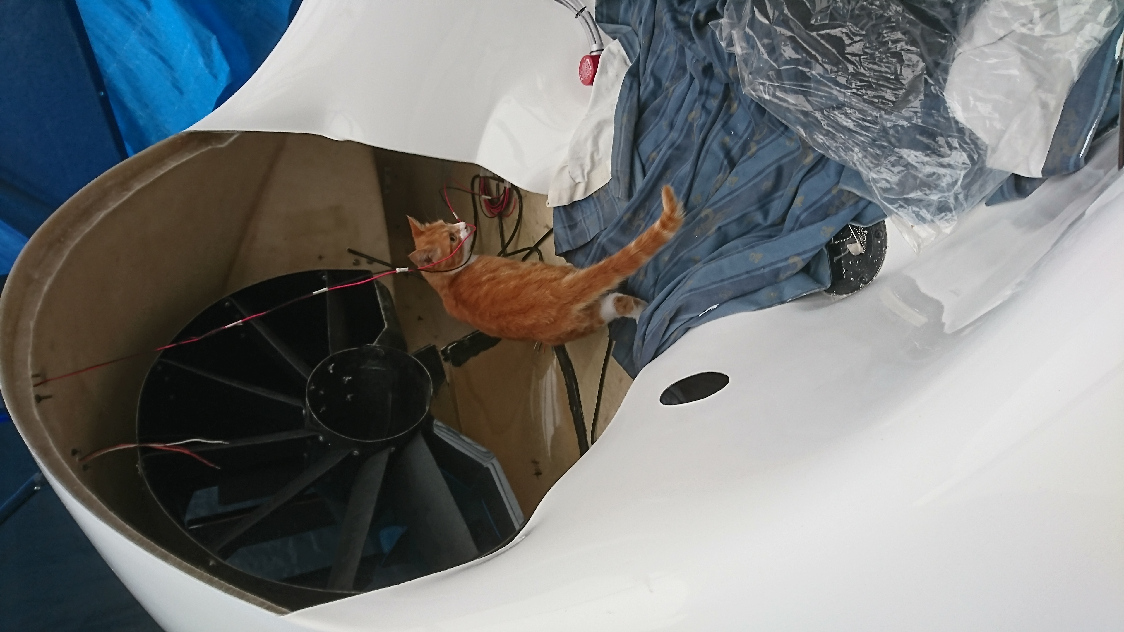
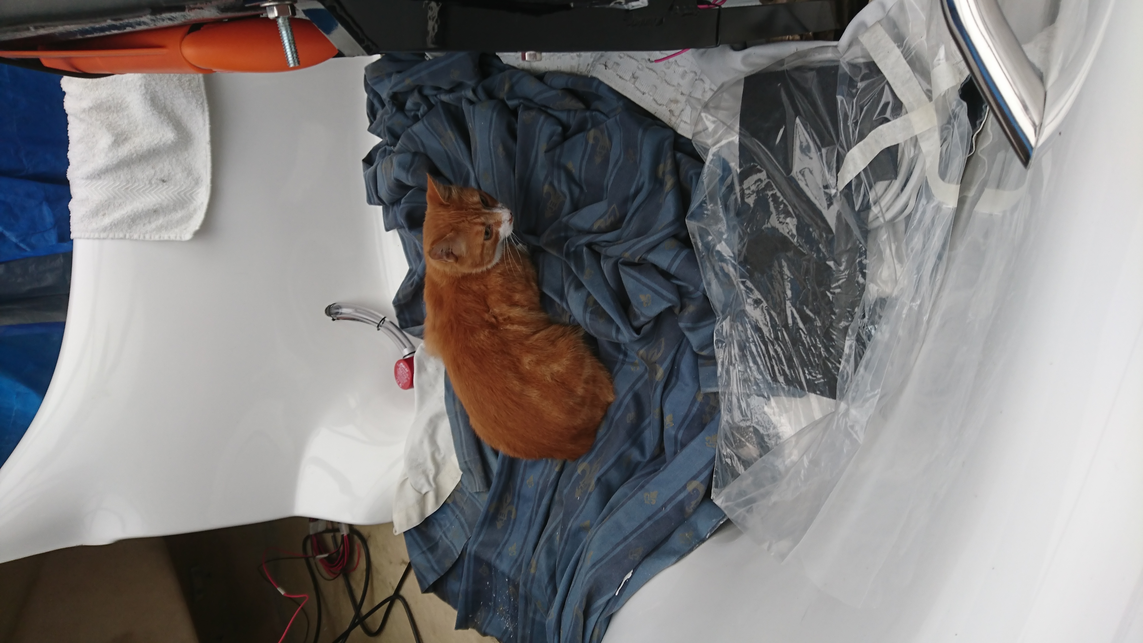
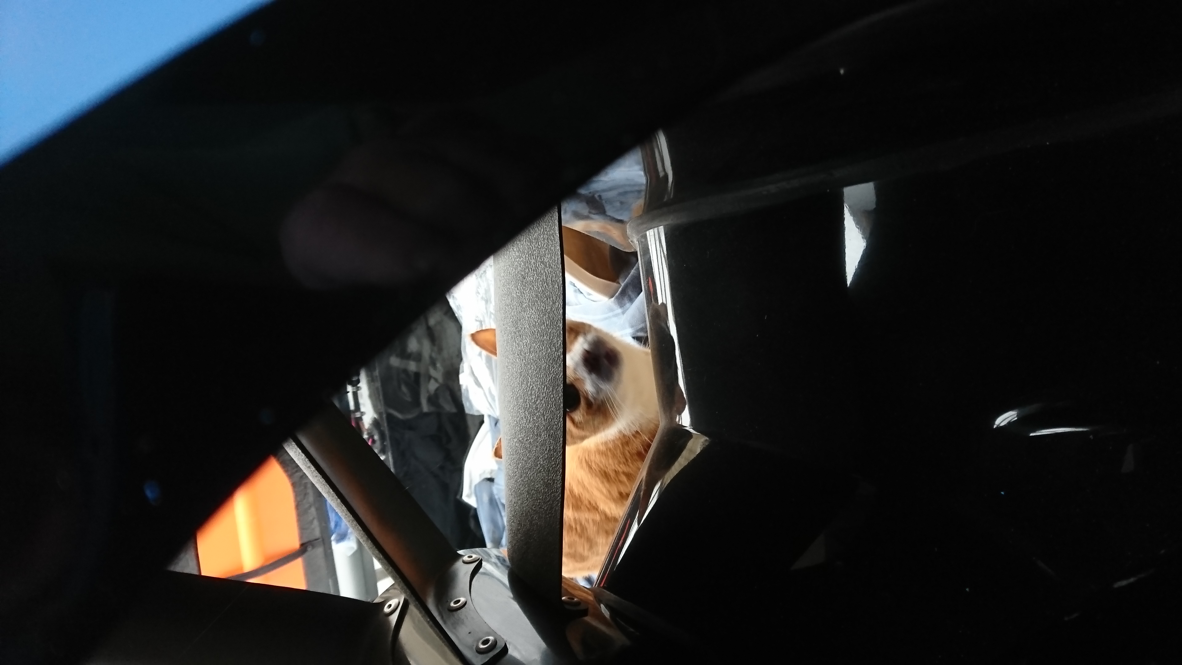
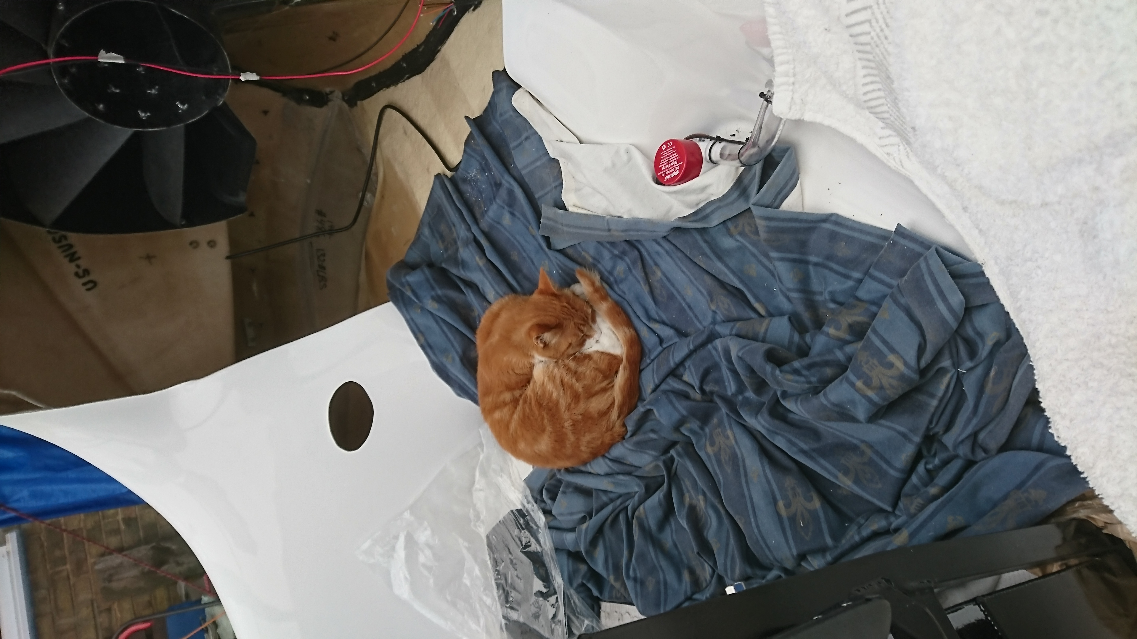
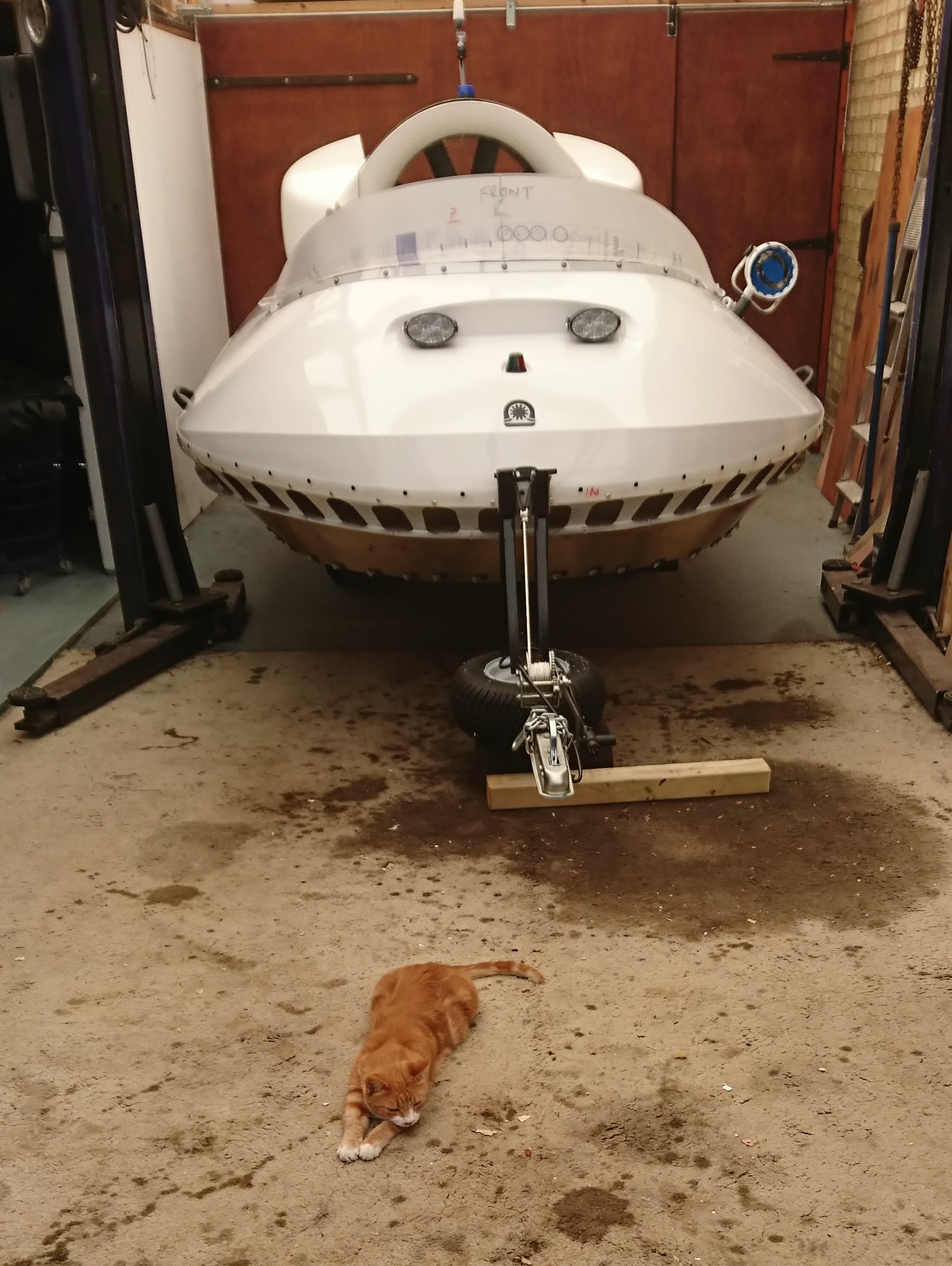
17. Ginger-Puss
Well Ginger Puss is like any other cat, inquisitive. He naturally wanted to know what was going on so he spent many hours just watching and snoozing – great company!
Ginger-Puss likes the power unit cover
The Boss just on his daily inspection
No mice in here,what's that wire doing
Hard work checking all this out,time for a snooze
18. Miscellaneous
I think the captions/file names say it all. In the event I decided not to fit a tow-bar to the Scootacar……..as if! Keys all on key life-rafts. Solar panel charger – see photo. No 25 in Wiring Section. See fuel tap on/off in Miscellaneous.
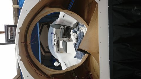
Front view awaiting skirt
Another front view awaiting skirt,by now it's grown 'ears' at the rear
Marking out Starboard splitter plate
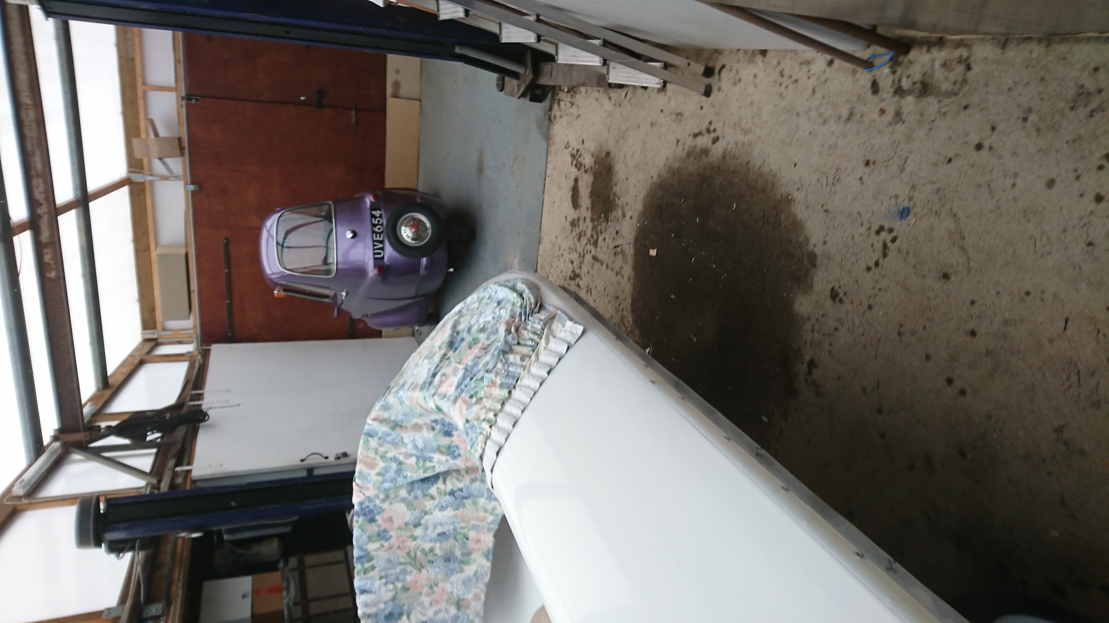
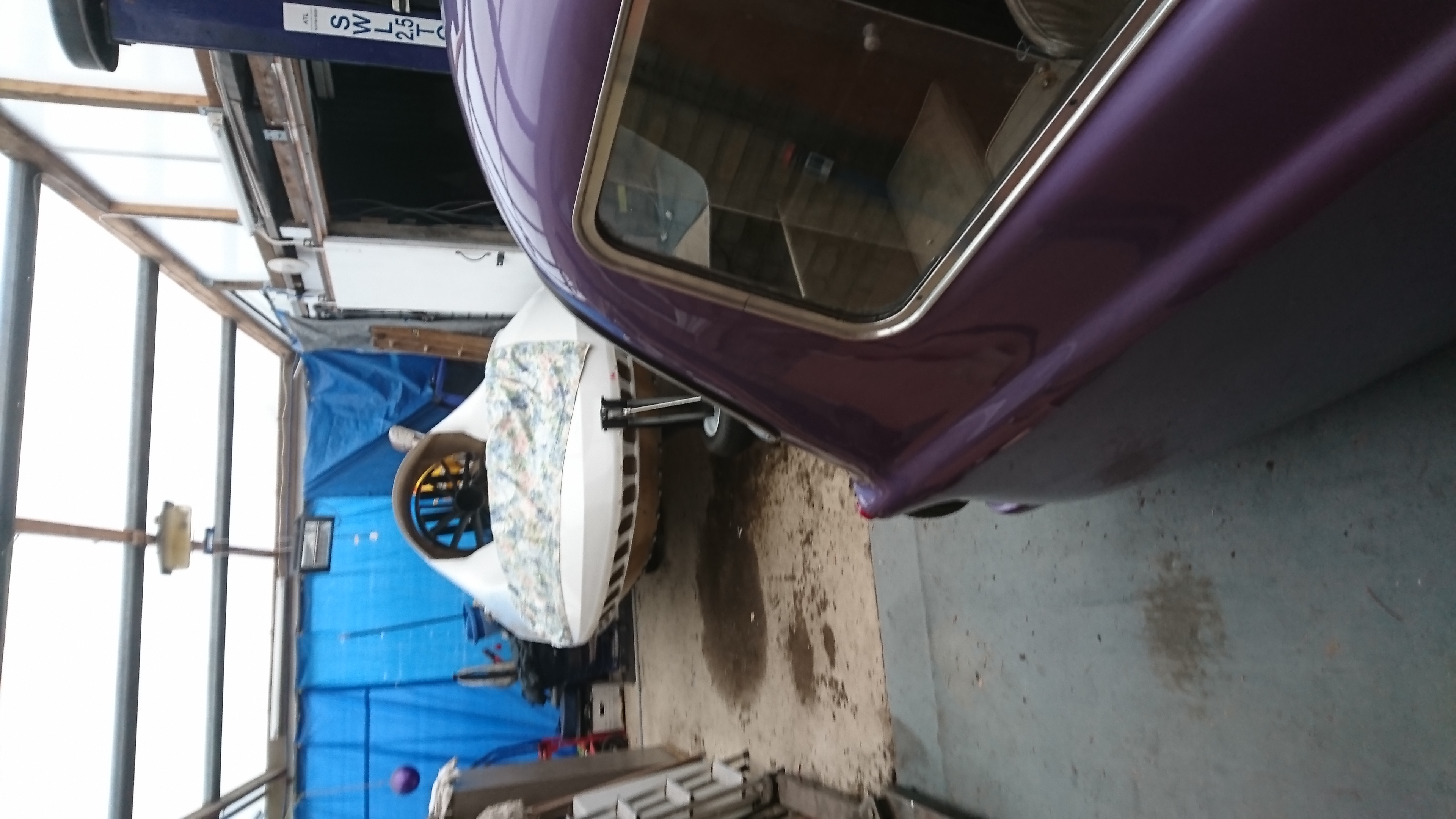
Scootacar sharing the lift shed
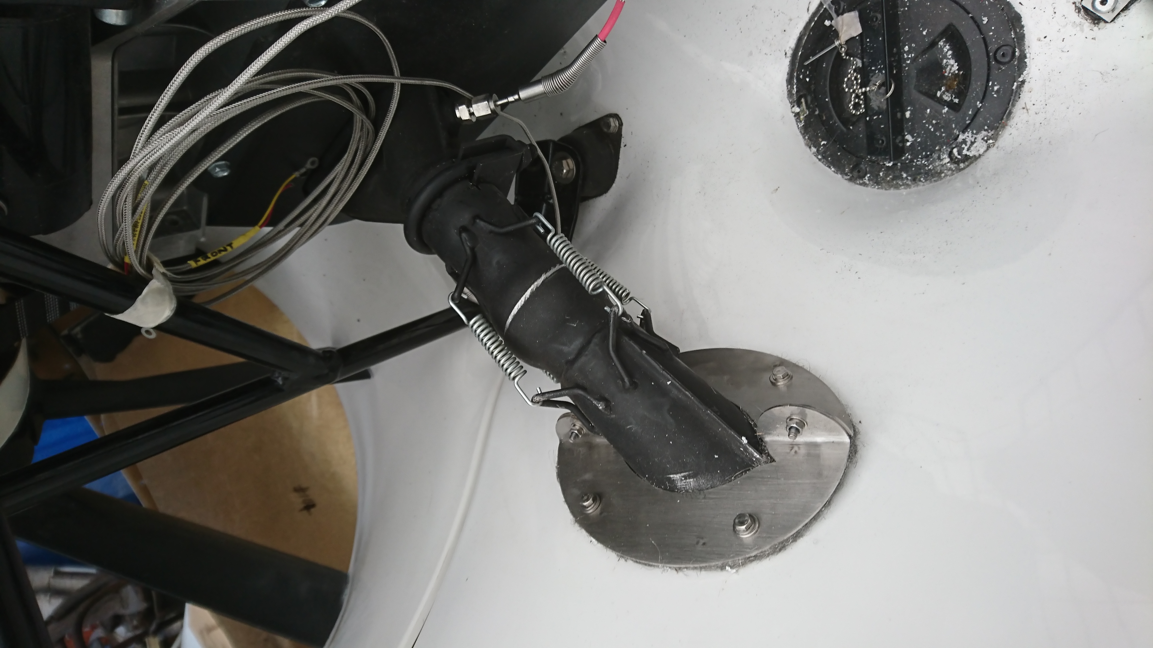
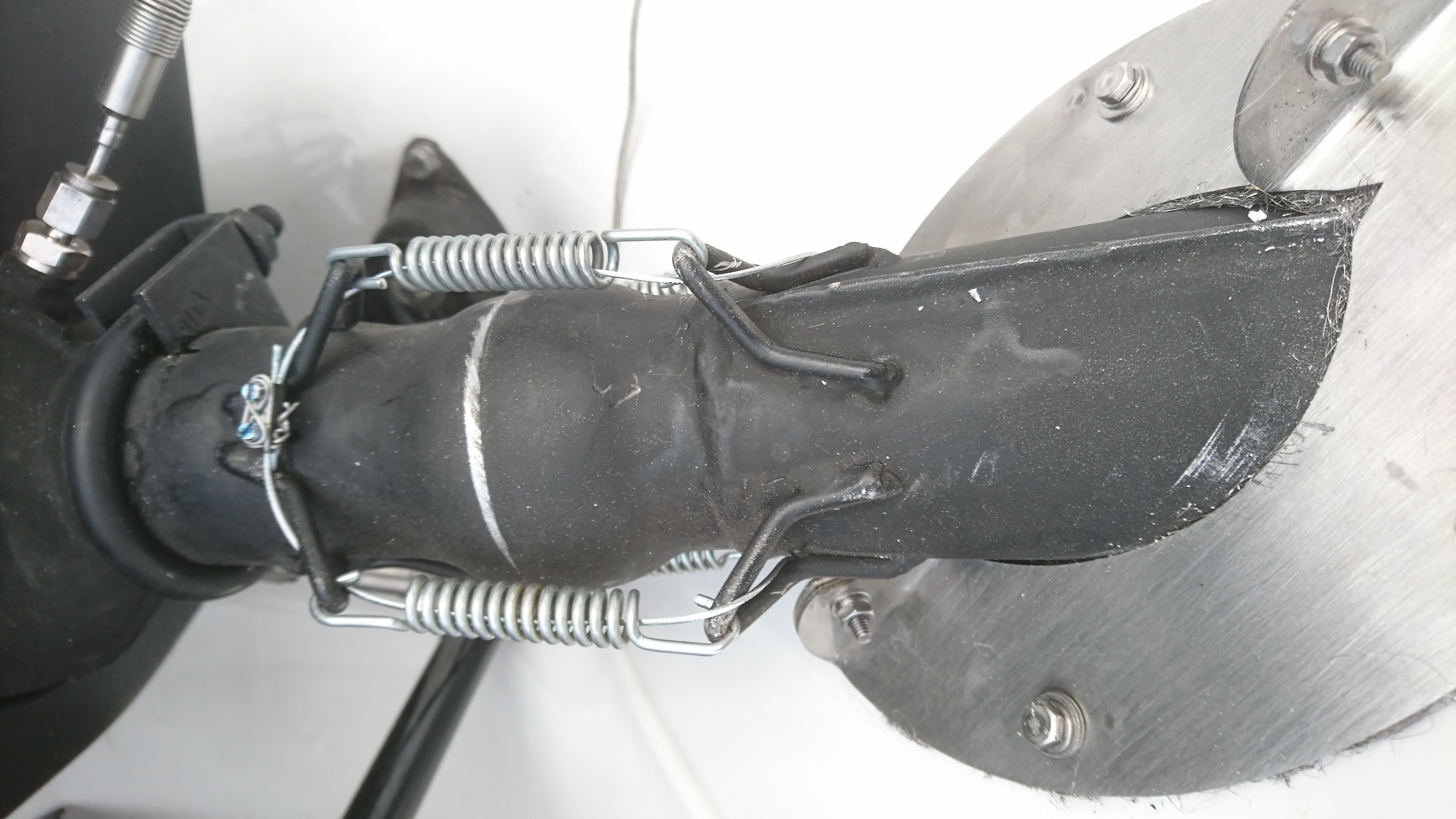
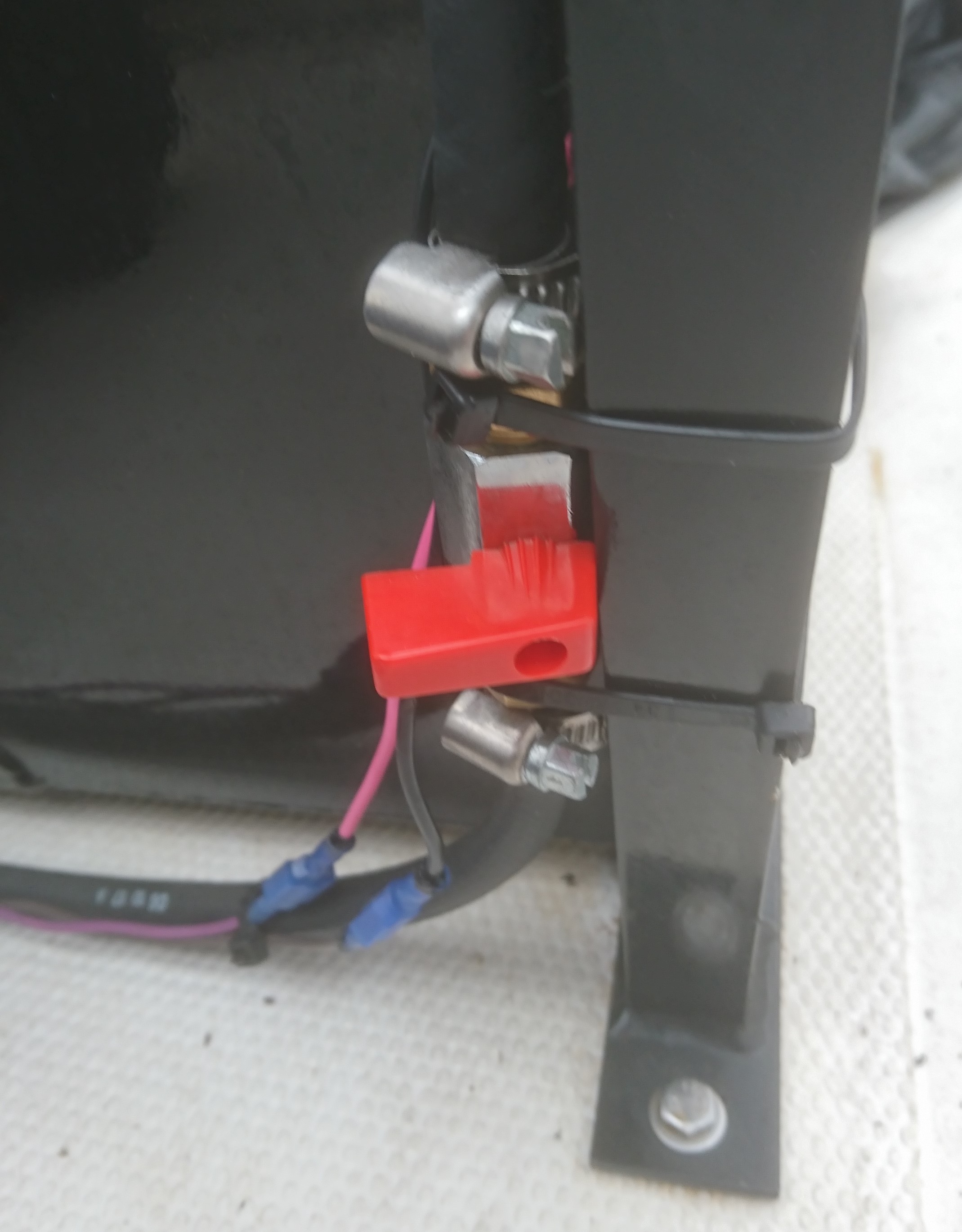
Fuel tap fitted to rear seat leg. Photo shows tap in the OFF position,ON is straight down.You can just see the Liquid Electrical Tape in the two wires shown below tap
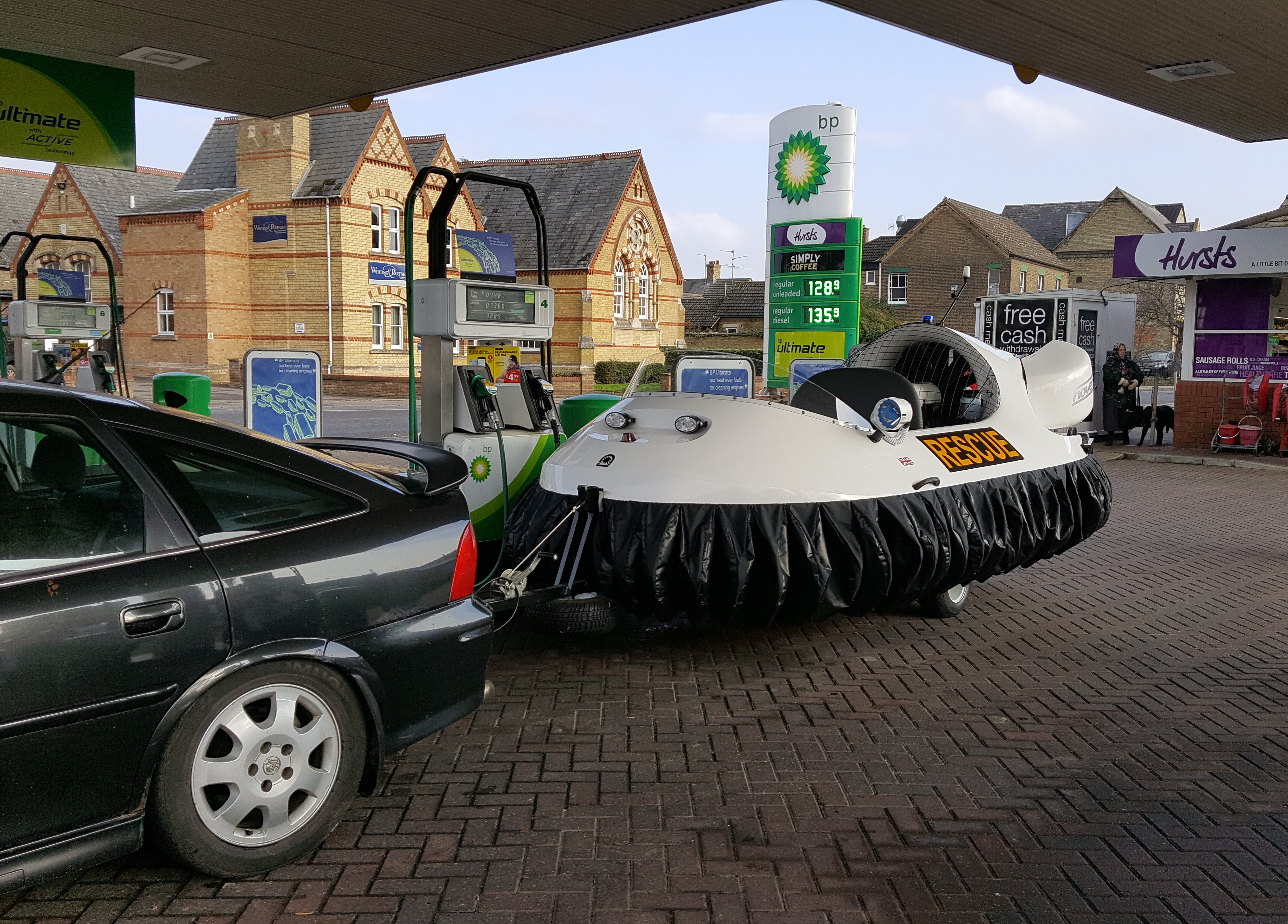
Refuelling at local petrol station