RESOURCES
About HovercraftYour product is FUN!!! It is a joy to drive (ride) it. I'll consider myself a full-blown expert Hovertrek™ pilot after about a year or so of daily practice! Boy, this craft really forces you to think 3D because all the surfaces that appear to be flat (more or less) prove themselves to be sloped when you fly the hovercraft over them. Wind and water current add to the complexity of telling the craft where you want it to go. But the reverse thrust system is "God's gift" for light hovercraft. It is amazing how much more control this system gives the pilot. What a pleasure to drive it. As a novice pilot, I am now able to hover in place, even on sloped beaches, and move where I want (as long as I have about 10 meters space). I semi-confidently park it slowly between my 2 boats at the marina with about 5-meter-width space. The skirt design with the cable ties works out really good. The cable ties give way first and are easily replaceable.
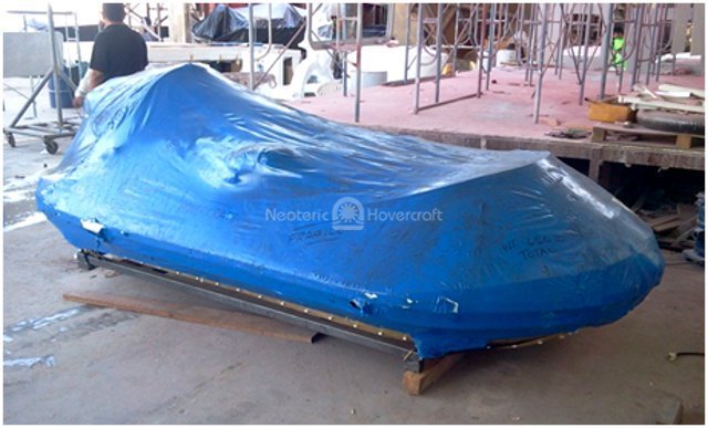
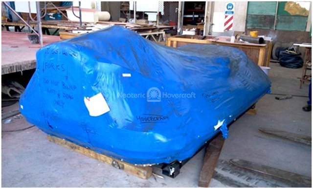
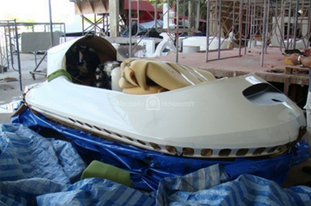
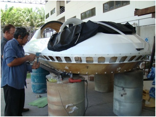
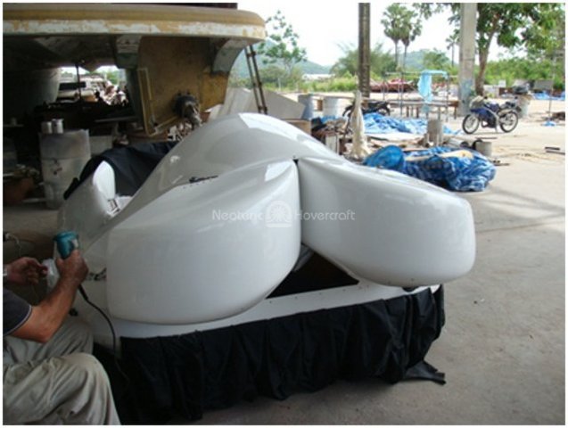
Here is our partially assembled Hovertrek kit when it arrived at our friend’s shipyard…
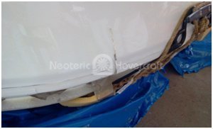
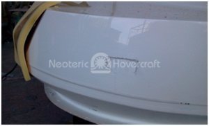
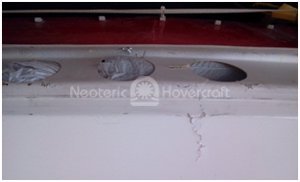
We inspected and found several GRP damages around the body; it looked like transport damage. Considering that the shipping crate was replaced with a (too small) steel pallet, we were surprised that the damage was not greater. A crate would have protected the thin fiberglass much more. The rudder was also damaged, but this could be bent back into place. There was even a hole in the bottom close to the exhaust.
Checking throughout the craft, we found every item on the packing list. Good, then let’s start the FRP repairs and the assembly of the craft using the supplied instruction manual. The first page of the manual said to go online to download an updated version. We had already downloaded it and we used the online version and the video to assemble the craft. (The video was outdated and confused us when assembling the engine; the mounting system had been revised.)
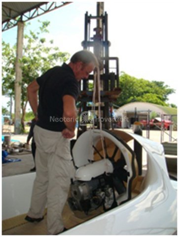
It took awhile to figure out how to fix the collar and use the foam. The exhaust did not line up unless we moved the engine back about 10mm, but then the mounting shocks didn’t line up with the fiber stands.
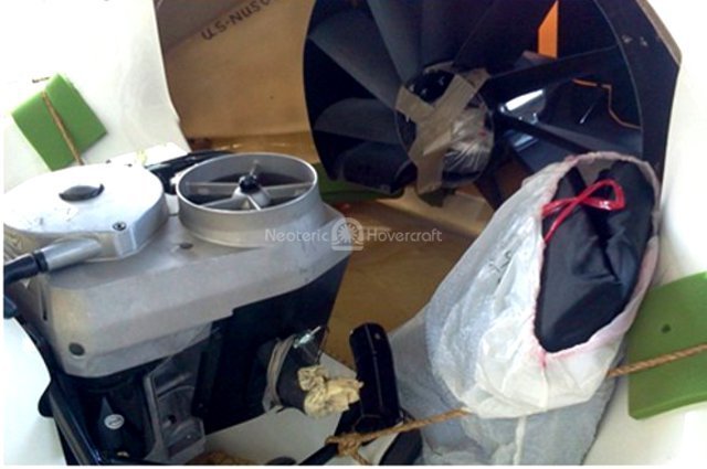
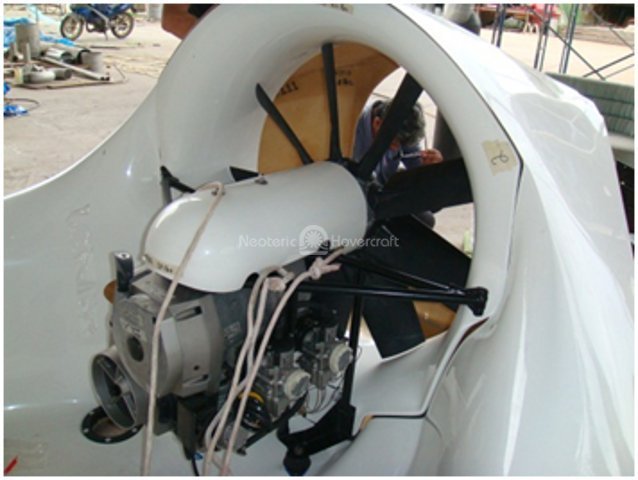
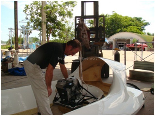
We did not remove the spark plugs before attempting to install the engine unit, but they are easily damaged during the installation. (It’s better to remove them.) We found an acceptable engine position where the bell house would more or less match the hull, and the engine supports were in the right place. The collar and foam patches secure the engine and reduce vibration. Our first mounting shock hole ended up half on the support beam on the underside of the craft; no way to get a nut on there so we realigned the mounting shock to get the holes right. And the engine was in place.
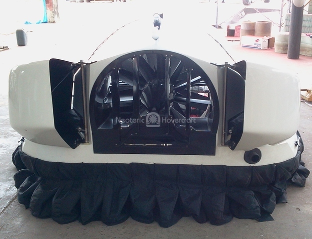
The black stator part did not match the engine bell house; we had a 15mm gap all around so we decided to laminate another 10mm to the black stator housing and use the thick foam to cover the other 5mm. We removed the stator and engine again to do other work.
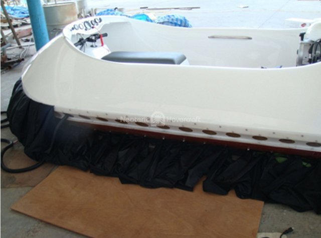
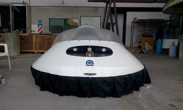
We then assembled the skirt system. We checked the parts and started to rivet the Teflon strip from the front on backwards. At the back we noticed that there were no holes pre-drilled in the remaining strip and, after measuring carefully, we realized that we had to figure out the hole spacing ourselves. There was simply not enough space left for the “fingers-spacer washer-finger-spacer washer” on the back. We ended up not using the plastic spacer rings (but maintaining the necessary offset space) at the back on the top rivets in order to gain space for all fingers.
This skirt system would prove itself very effective in usability, quick repair and maintainability.
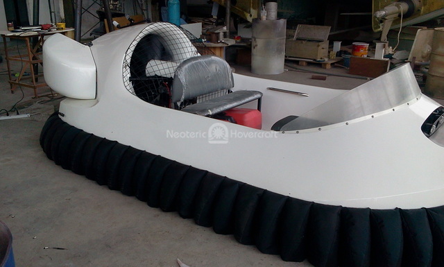
After the skirt system was installed, we moved on to the seats. Both manuals state that the 4-person inline seat position is referred from the back of the cockpit but that wasn’t useful for us as we have a combination seat system, and the side-by-side back seat position is referred from the front side-by-side seat. It wasn’t clear where to mount both a front inline and back side-by-side seat.
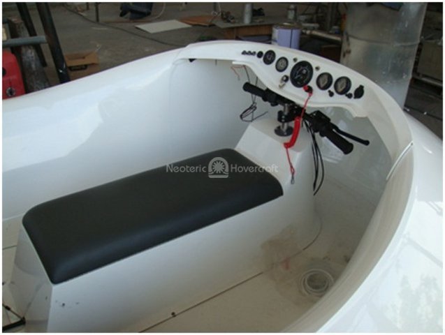
The video and pictures, however, helped us to find the right position for the front inline seat. The steering column is right under the instrument panel. To install the back seat, we decided to move the seat backward as far as possible so that the engine mess would still open and to have a roomy cockpit. Too bad that we have the steering, throttle and choke cables running over the floor! We mounted the two fuel tanks under the seat and the battery box in between, as well as the electrical plate with splash cover behind the battery box.
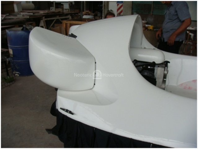
It took us a while before we realized that we had a new computer that controlled the reverse thrust buckets. Once it was clear to us, we had no problem fixing all parts together and they work perfectly. The bucket installation was easy and after drilling a wrong hole for the bucket support struts we had them working in no time. (One more actuator could do the same for the rudder…)
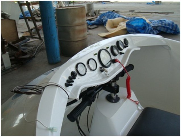
The instrument panel assembly was another hurdle. We ended up not mounting the hour meter on the panel; there is no space other then on a curved section of the panel. (A combination rpm/hour meter might be better.) The hour meter will probably end up next to the steering column. We rearranged the instruments a bit without realizing that the wiring harness was made for the original layout, so we modified that a bit too. We didn’t see assembly instructions on the instrument panel and the windshield but we figured that they should be mounted together, so we did. The rest of the accessories were assembled to the craft without any issues.
Concluding the assembly process, we found (as first time Hovertrek builders) that the manuals and video were helpful and confusing at the same time, but we wanted a partly assembled kit to gain knowledge about the technique and development of this craft. We certainly achieved that and Neoteric created a beautiful product.
After about 10 days of assembling, we were ready to do our first test run on the yard’s hard deck with many obstacles. It appeared that throttling up to 3000 rpm, our craft was heavy in the back with only one tank filled and an 87Kg person in control; we needed a 20Kg extra weight in the front to balance it.
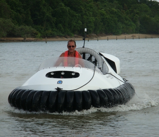
Our first real trials were scary to say the least. Our maiden trip’s first challenge was to maneuver it on the hard deck, toward a narrow slipway, into the marina waters, to the river and out to the sea for a 25-mile journey - with no hovercraft experience at all. (Don’t do this at home, kids!)
By the time we arrived, we knew that we had to drive this craft a lot more to master it. But what an impressive craft!
We drove the craft about every day for almost two months on beaches, mud, mangroves and at sea. We now clocked about 60 hours and enjoyed every minute of it, including self-induced heavy showers and plow-ins. We still have an issue with the engine fuel mixture between 4000 and 5200 rpm, going about 30 knots on flat sea at 5200 rpm. Decreasing the power a bit to reduce speed would make the engine drop from 5200 below 4000 rpm because of fuel mixture issues, dropping the cushion pressure and creating a plow-in situation.
The only issue with the craft is the noise level. Every bit of noise reduction seems worth a try. Apart from that, the more we drive it, the more we are impressed with the handling and maneuverability.
Some thoughts we have about alterations: